Teledyne Continental Motors, Inc.
TM
Non-Overhaul Removal and Replacement
IOF-550 Permold Series Engine Maintenance Manual
10-35
1 April 2007
Header Shell
25 Pin
Connectors
Header Shell
25 Pin
Connectors
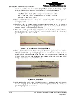
Figure 10-30.
Typical SSA Conditioner 25-pin Connector
5.
Apply Alodine to the connector header shell contact area in accordance with the
Alodine manufacturer’s instructions. Allow the Alodine to dry.
6.
Clean the connector header face with mild solvent. Inspect for contamination.
CAUTION: Do not directly apply liquid cleaning agents to the
connector header as the pin socket may fill with fluid. Sparingly
apply cleaner to cleaning cloth.
7.
Inspect the engine low voltage harness connector for contamination, deformed pins,
or any observable discrepancies. If the old seal is observed at the base of the
connector pins, remove with tweezers.
8.
Check the resistance between the connector(s) header (Figure 10-31) and airframe
electrical ground. The resistance must be less than 0.5 ohms.
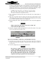
Figure 10-31.
Engine Low Voltage Harness 50-Pin Connector
WARNING
High resistance indicates a FADEC ground fault. Correct the
grounding fault before ECU or signal conditioner installation.
9.
Check the resistance between the connector(s) header and the engine. The resistance
must be less than 0.5 ohms.


