Non-Overhaul Removal and Replacement
Teledyne Continental Motors, Inc.
TM
10-48
IOF-550 Permold Series Engine Maintenance Manual
1 April 2007
6.
Grasp the solenoid coil and lift it from the fuel injector body.
CAUTION: Do not separate the coil body from the injector body by
pulling on the harness lead wire. Pulling on the harness lead can
cause permanent, irreparable damage to the injector coil which may
result in engine malfunction.
NOTE: A Borroughs 8165 Injector Remover and Installer may be
used to remove the fuel injectors.
7.
Use a deep-well socket to remove the injector body from the cylinder.
8.
Place protective caps on the fuel injector body.
10-6.11. Fuel Injector Installation
CAUTION: Avoid introducing contaminants into the fuel injectors.
Work with clean hands, tools, and shop towels. Place protective
caps on the fuel injectors anytime the fuel line is not connected.
Never insert an object into either end of a fuel injector.
Procedure
1.
Flush the injector’s fuel line by placing the injector end of the line in a small
container and activating the aircraft fuel boost pump. Flush a minimum of 100 ml of
clean, filtered aviation fuel through the line. Before emptying the container, visually
inspect contents for signs of contamination. If foreign debris is observed, repeat the
flushing process.
2.
Visually inspect the cylinder head injector boss threads for signs of deformation.
3.
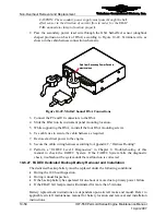
Apply small amount of anti-seize compound to the second and third injector
mounting thread (Figure 10-43).
DO NOT APPLY F/I
ANTI-SEIZE TO THE FIRST
TWO THREADS
APPLY ANTI-SEIZE
SPARINGLY HERE
TAPERED END
Figure 10-43.
Anti-Seize Lubricant Application on the Fuel Injector
4.
Thread the injector body into the cylinder head by hand. Use a deep-well socket or
Borroughs 8165 Injector Remover and Installer to torque the fuel injector according
to Appendix B.
5.
Install the fuel injection solenoid coil according the instructions in section 10-6.12.
“Fuel Injection Solenoid Installation.”


