Non-Overhaul Removal and Replacement
Teledyne Continental Motors, Inc.
TM
10-58
IOF-550 Permold Series Engine Maintenance Manual
1 April 2007
CAUTION: The secondary power supply must pass through the hall
effect sensor in the direction of current flow in order for the EBAT
FAIL annunciator lamp to function properly.
2.
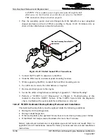
Pass the secondary power lead wire through the HSA hall-effect sensor (doughnut
shaped protrusion on back of HSA) according to Figure 10-49. Terminate wire as
shown in the cabin harness connection schematic.
Path from Secondary Power Switch to
electrical bus
Path from Secondary Power Switch to
electrical bus
Figure 10-49.
Multi-Channel HSA Connections
3.
Connect the P9 and J10 connectors to the HSA.
4.
Slide the HSA into its instrument panel mounting location.
5.
While supporting the HSA, re-install the four HSA mounting screws.
6.
Use cable ties to secure the cabin harness as required.
7.
Restore electrical power to the engine.
8.
Secure the cabin wiring harness according to Appendix C, “Harness Routing.”
9.
Perform a “FADEC Level I Diagnostics” in Chapter 8, Troubleshooting of this
manual to check the FADEC System. If the FADEC System fails the diagnostic
check, troubleshoot the system until the malfunction is corrected.
10-6.27. FADEC Dedicated Backup Battery Removal and Installation
The dedicated backup battery must be replaced under the following conditions:
•
During the 100 hour Inspection
•
During Annual Inspection
•
If the backup battery has operated for one hour or more due to primary power failure
•
If the EBAT fail lamp remains illuminated for more than 5 minutes
Battery replacement instructions are dependent upon aircraft make and model. Refer to
applicable aircraft maintenance manual for battery location and removal and installation
instructions.


