Non-Overhaul Removal and Replacement
Teledyne Continental Motors, Inc.
TM
10-92
IOF-550 Permold Series Engine Maintenance Manual
1 April 2007
19.
Install the Induction and Exhaust System components according to instructions in
Chapter 11, Engine Assembly of the Overhaul Manual (OH-24) and applicable
airframe manufacturer’s instructions.
20.
Install the Fuel Injector according to instructions in Section 10-6.11.
21.
Install the Fuel Injector Solenoid according to instruction in Section 10-6.12.
22.
Set the aircraft Fuel Selector Valve to the ON position and activate the fuel boost
pump and leak check the fuel delivery system, including fuel lines and fittings.
23.
Service the engine with mineral oil by following the steps in the section “Oil Change
Procedure” in Chapter 9. Be sure to use mineral oil for cylinder break-in.
24.
Install the aircraft cowling and airframe-supplied accessories according to the
airframe manufacturer’s instructions.
25.
Perform the tasks listed in Chapter 6, Operational Performance Checks.
26.
Perform the steps in the “25-hour Initial Operation Inspection” in Chapter 7 at the
designated interval. When oil consumption has stabilized, replace the mineral oil with
ashless dispersant aviation engine oil by following the steps in the “Oil Change
Procedure” in Chapter 9.
10-8.8. IOF-550-N, P and R Engine Cylinder Installation
Procedure
1.
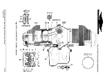
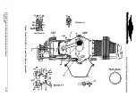
Refer to Figure 10-61; install a new cylinder base O-ring (59) lubricated with aviation
engine oil. (Verify the cylinder base O-ring is free of cracks and deformities.)
2.
Thoroughly clean the cylinder deck and stud threads with Stoddard solvent; use a
narrow brush to clean stud thread holes. The deck and stud holes must be free of all
dirt and debris.
3.
Lubricate all cylinder through bolt and deck stud threads using clean 50 weight
aviation engine oil.
4.
Verify the piston rings (56 through 59) have been installed on the piston and partially
installed in the cylinder bore and a new cylinder base O-ring (59), lubricated with
aviation engine oil, has been installed on the cylinder flange.
5.
Carefully rotate the crankshaft placing the connecting rod of the cylinder being
installed in the outer most position. Remove the O-ring that was installed for the
connecting rod support.
6.
Back the piston pin (60) out far enough to allow the piston (55) to be installed on the
connecting rod.
7.
Place the cylinder and piston (55) on the connecting rod.
8.
Line the piston up with the connecting rod and slide the piston pin into the connecting
rod.
9.
Using a ring compressor, compress the fourth piston ring and push the cylinder until
the fourth piston ring is positioned inside the cylinder barrel.
10.
Remove the ring compressor and push the cylinder assembly against the crankcase
cylinder deck with the stud holes aligned.


