Troubleshooting
Teledyne Continental Motors, Inc.
TM
8-5.
Charging System
Refer to the airframe manufacturer's applicable troubleshooting information for the
Charging System.
8-6.
FADEC System
8-6.1. FADEC Level I Diagnostics
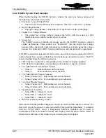
A FADEC System diagnostic check is required at the beginning of the 100-hour/Annual
Inspection and after troubleshooting. FADEC Level I Diagnostics requires:
•
A laptop PC computer with Microsoft Windows 95 or later operating system
•
TCM FADEC Level I Diagnostic Software installed on the PC
•
FADEC to PC Data Communication Cable (without EDI) or the Serial Data Cable
(with EDI) (See Chapter 3, Special Tools and Supplies)
Two interface methods are available to connect a personal computer with the
Electronic Control Units for viewing the engine operating parameters. The standard
configuration for FADEC Diagnostics is the FADEC serial data port (part of the
cabin harness). The serial data port allows real-time monitoring of engine operation
while the PC with Level I Diagnostic application loaded is connected to the serial
data port and the engine is running. A FADEC to PC Data Communication Cable is
required to interface with the FADEC Serial Data Port. The optional engine data
interface (EDI) provides the same functions as the FADEC Serial Data Port with the
additional feature of time-stamped engine data collection with fault history
throughout all periods of engine operation above 300 RPM until the removable EDI
memory is filled to capacity. The EDI faceplate incorporates a 2.5mm stereo jack
interface. The serial data port or optional EDI are cabin-mounted components, usually
beneath the instrument panel. Consult the aircraft maintenance manual for the
location of the serial data port.
NOTE: A USB to 9-pin adapter is available for computers without
a 9-pin serial connector.
Figure 8-1.
Engine Data Interface
8-12
IOF-550 Permold Series Engine Maintenance Manual
1 April 2007

