Teledyne Continental Motors, Inc.
TM
Maintenance and Adjustments
IOF-550 Permold Series Engine Maintenance Manual
9-21
1 April 2007
7.
Connect the lead wires as follows:
a.
Insert the spring-end of the lead into the spark tower.
b.
Hold the ferrule while firmly push the rubber insulator into the tower.
c.
When the B-nut thread makes contact with the spark tower threads, turn the B-nut
clockwise.
d.
Restrain the lead wire ferrule to prevent kinking of the lead.
e.
Continue rotating the B-nut until it seats.
f.
Torque the B-nut per Appendix B.
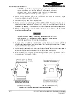
CAUTION: Do not allow the ignition lead wire outer jacket to twist
while tightening the B-nut. If twisting is observed, hold the knurled
portion of the B-nut shoulder stop piece with an open-end wrench
while tightening the B-nut.
8.
Support the ignition leads with clamps and cable ties; allow no more than 8 inches
between unsupported sections. Secure the harness leads together with the EGT and
CHT leads at lower locations.
9.
Route leads as far away as possible from exhaust pipes to ensure they are not exposed
to temperatures in excess of 400°F (204°C).
10.
Route the ignition leads with the bundled wiring of the engine low voltage harness to
provide additional support. Adhere to the guidelines in Appendix C, “Harness
Routing” Use cable ties to neatly bundle and secure the ignition leads to the engine
and airframe.
9-5.
FADEC Dedicated Backup Battery Replacement
If a dedicated FADEC System backup battery is used as a secondary power source, it
must be replaced in the following circumstances:
•
Every 12 calendar months after the date of installation
•
If the backup battery is severely depleted
•
If the EBAT FAIL lamp stays illuminated for more than 5 minutes on the HSA panel.
The backup battery is an airframe component. Refer to airframe maintenance
documentation for battery location and removal and installation instructions.
9-6.
Throttle Control Linkage Rod Maintenance
Inspected the throttle control linkage according to “Engine Control Linkage Inspection”
in Chapter 7, Maintenance Inspections to ensure proper operation and prevent accelerated
wear. Replace worn or corroded linkage or attaching hardware in accordance with the
TCM’s Overhaul Manual (OH-24).
Procedure
1.
Clean dirt and debris from pivot points of levers and linkages using clean Stoddard
solvent. After cleaning, dry each area using compressed air.
2.
Check the components, rod, and linkages for wear or corrosion. Replace worn or
corroded linkages or attaching hardware.

