Non-Overhaul Removal and Replacement
Teledyne Continental Motors, Inc.
TM
10-12
IOF-550 Permold Series Engine Maintenance Manual
1 April 2007
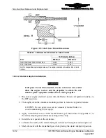
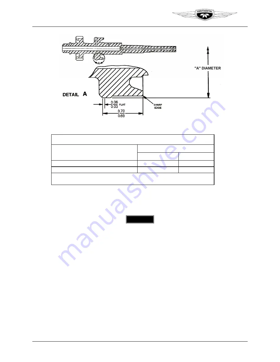
Figure 10-5.
Shaft Gear Drum Dimensions
Table 10-7.
Shaft Gear Drum Dimensions: Fits and Limits
“A” Diameter (inches)
Part
Minimum Maximum
New Shaft Gear Drum Dimensions
1.931
1.932
0.015 Undersize
1.916
1.917
NOTE: Inspect the start adapter sleeve. The outside diameter should be .812 to .814
inches.
10-3.4. Starter Adapter Installation
Procedure
WARNING
If all power is not disconnected, a loose or broken wire could
allow the engine to start and the propeller to rotate. Do not
stand or place equipment within the arc of the propeller.
1.
Disconnect engine electrical power; turn the Master Power and Ignition Switches to
the OFF positions.
2.
Thoroughly clean the crankcase mounting surface to remove any gasket residue.
CAUTION: Do not apply an excessive amount of Gasket Maker to
avoid contaminating the oil supply.
3.
Apply a translucent coat of TCM Gasket Maker (per instructions in Appendix C) to
the starter adapter gasket crankcase mating surface only.
4.
Install the new gasket on the crankcase.
5.
Lubricate the teeth on the starter shaft gear with clean 50-weight aviation engine oil.
6.
Mesh the teeth with the crankshaft gear while placing the starter adapter in position.


