Teledyne Continental Motors, Inc.
TM
Engine
Description
IOF-550 Permold Series Engine Maintenance Manual
2-11
1 April 2007
2-2.3.1. Pistons
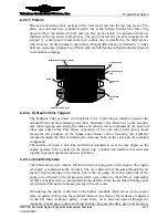
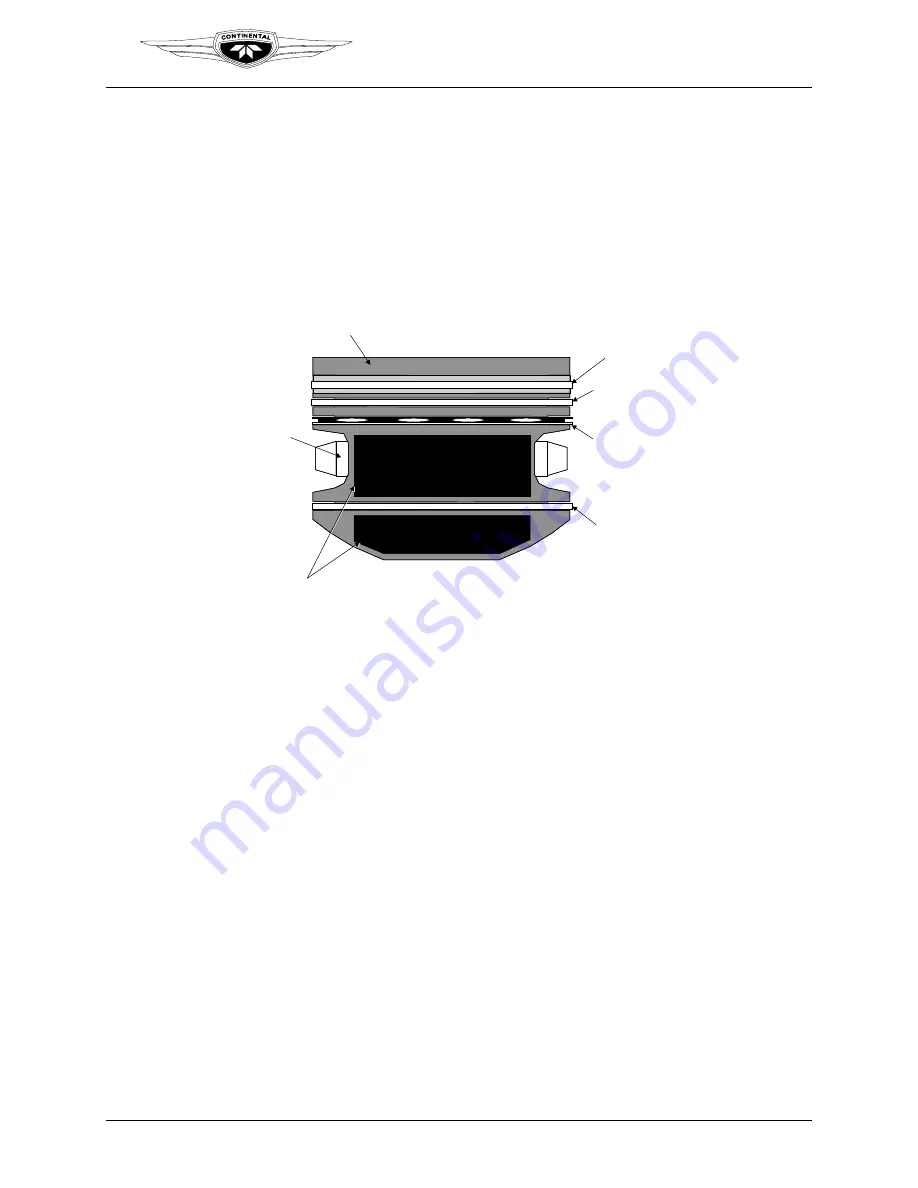
Pistons are aluminum alloy castings with a steel insert cast into the top ring groove. The
skirts are solid and have cylindrical relief cuts at the bottom. Pistons have three ring
grooves above the piston pin hole and one ring groove below. Compression rings are
installed in the top and second grooves. The groove below the pin hole contains an oil
scraper. A center grooved and slotted oil control ring is installed in the third groove
which has six oil drain holes to the interior. Weight differences are limited to ½ ounce
between opposing cylinders bays. Piston pins are full floating with permanently pressed-
in aluminum end plugs.
PISTON PIN
MANGANESE PHOSPHATE COATING
GRAPHITE COATED SKIRT
1
ST
COMPRESSION
RING
2
ND
COMPRESSION
RING
OIL CONTROL
RING
OIL SCRAPER
RING
2-2.3.2. Hydraulic Valve Tappets
The hydraulic lifter performs two functions. First, it provides an interface between the
camshaft lobe and the remaining valve train. Hydraulic valve lifters ride on the eccentric
cam lobes opening and closing the intake and exhaust valves mechanically via push rod
tubes and rocker arms. This allows conversion of the cam lobe profile into a linear
movement for actuation of the intake and exhaust valves. Secondly, the hydraulic
mechanism inside the lifter maintains zero clearance between the valve and it’s actuating
components.
The interface between a cam lobe and lifter is intended to wear to some degree as the
engine operates. This is similar to the piston ring / cylinder wall interface that must seat
together for proper operation and wear over time.
2-2.4. Lubrication System
The lubrication system reduces friction between moving parts in the engine. The engine
oil supply is contained in the oil sump. The oil is drawn from the sump through the oil
suction screen and tube to the intake side of the oil pump. From the outlet side of the
pump, oil is directed to the oil pressure relief valve, and on to the full flow, replaceable
oil filter. A bypass valve is incorporated in the oil filter. From the oil filter discharge port,
oil is directed through a crankcase passage to the oil cooler.
Oil entering the engine is directed to the hollow camshaft which serves as the engine
main oil gallery. Oil leaving the camshaft interior at the front of the crankcase is directed
to the left main crankcase gallery. From there, oil is directed upward through the
crankcase oil passages to the main thrust bearing, the governor drive gear, and accessory


