Teledyne Continental Motors, Inc.
TM
Non-Overhaul Removal and Replacement
IOF-550 Permold Series Engine Maintenance Manual
10-45
1 April 2007
10-6.9.
SSA Operational Check
Procedure
1.
Turn the Aircraft Master Power Switch, Ignition Switch, and the FADEC Primary
Power and Secondary Power Switches to the OFF position.
2.
Disconnect the high voltage harness and remove the top spark plugs from all
cylinders; see “Ignition System Maintenance” in Chapter 9 of this manual for detailed
removal instructions.
NOTE: The N
c
and N
e
switches enable audio associated with LED
illumination. Position all N
c
and N
e
switches closest to its
representative LED indicator to turn off audio.
3.
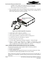
Remove the safety wire and disconnect the clamp from the 13-pin sump connectors
on both sides of the engine. Remove the 13 pin connectors. Connect the 13-pin
interface cable between the FADEC Timing tool Figure 10-40 and the jack on the 2-
4-6 side of the engine.
To 2-4-6 side
connector on
sump
Figure 10-40.
FADEC Timing Tool to Sump Connector
4.
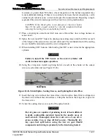
Turn on the FADEC Timing Tool by sliding the power switch toward the top of the
tester. The power LED will illuminate to indicate power is on. The N
c
and N
e
LED
state will depend on sensor position in relation to the camshaft. LEDs are normally
ON; as the holes in the camshaft pass the sensor, the LED will extinguish
momentarily.
R
P
N


