Non-Overhaul Removal and Replacement
Teledyne Continental Motors, Inc.
TM
10-50
IOF-550 Permold Series Engine Maintenance Manual
1 April 2007
10-6.13. Manifold Air Pressure Sensor Removal
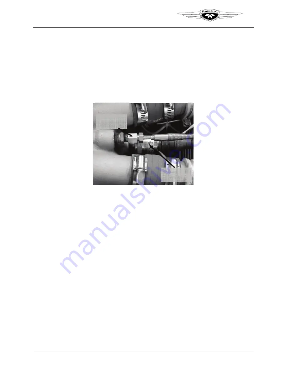
Two Manifold Air Pressure (MAP) Sensors install near the throttle body. The MAP
Sensors thread into tapped bosses. Your engine application may vary from those shown
in Figure 10-44.
The MAP Sensors attach to the engine low voltage harness using circular connectors.
The MAP Sensors are not field serviceable or repairable. If the sensor malfunctions or
fails it must be replaced.
MAT
Sensor
MAP
Sensor
MAT
Sensor
MAP
Sensor
Figure 10-44.
Manifold Air Pressure Sensor
Procedure
1.
Disconnect electrical power to the engine.
2.
Cut and remove cable ties as necessary to remove the connector from the sensor.
3.
Disconnect the engine low voltage harness circular connector from the pressure
sensor.
4.
Place a protective cap on the engine low voltage harness connector.
5.
Unthread the pressure sensor from the throttle body.
10-6.14. Manifold Air Pressure Sensor Installation
Procedure
1.
Disconnect electrical power to the engine.
2.
Apply Thread Sealant to the second and third threads of the pressure sensor.
3.
Visually inspect the mounting threads for deformation.
4.
Thread the sensor into the mounting boss on the throttle body. Torque the sensor per
values in Appendix B.
5.
Using a DVM, measure the resistance between the engine low voltage harness
connector body and airframe electrical ground bus. Resistance must be less than 0.5
ohms.


