Teledyne Continental Motors, Inc.
TM
Non-Overhaul Removal and Replacement
IOF-550 Permold Series Engine Maintenance Manual
10-55
1 April 2007
1.
Place new EGT sensor in location to be installed. Route wires along path of final
installation to determine length of installed harness. Trim sensor leads to of new
sensor and harness leads to closely approximate the length of the original wire.
2.
Connect the new sensor to the engine low voltage harness using the instructions in
Section 10-5.1, “EGT Sensor and Lead Wire Replacement.”
3.
Route the EGT sensors for Cylinders 1-3-5 from the rear of the engine to the lower
right-hand quadrant of the engine and onto each sensor’s respective cylinder. Route
the EGT sensors for Cylinders 2-4-6 from the rear of the engine to the lower left-hand
quadrant of the engine and onto each sensor’s respective cylinder.
CAUTION: Each EGT sensor is identified and designated for a
specific cylinder. Be sure to install the correct EGT sensor for a
corresponding cylinder. Failure to install the EGT sensors on the
correct cylinder will result in abnormal engine operation.
4.
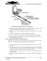
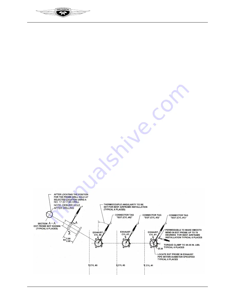
Place the sensor into the exhaust tube. Locate the EGT sensor probe in the exhaust
pipe within the diameter specified in Figure 10-48. Wrap each clamp around the
exhaust pipe and tighten the clamp to secure the sensor but not flattening the crimps
in the band against the outside surface of the exhaust pipe. The crimps accommodate
exhaust pipe thermal expansion during engine operation. Torque the sensor per torque
values in Appendix B.
5.
Ensure each EGT sensor is secured in the exhaust pipe by the clamp.
CAUTION: If the excess portion of the band comes in contact with
the sensor body, permanent damage could result.
6.
Trim any excess band clamp length (extending beyond the clamping nut) to within ¼-
inch of the worm screw body or fold the excess away from the EGT sensor body,
ensuring the excess does not contact surrounding components allowances.
Figure 10-48.
EGT Sensor Installation


