Teledyne Continental Motors, Inc.
TM
Non-Overhaul Removal and Replacement
IOF-550 Permold Series Engine Maintenance Manual
10-97
1 April 2007
5.
Align the screw holes in the boss and the rocker shaft (18) and install the screws (20)
(Figure 10-59) and plain washers (19).
6.
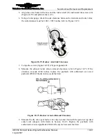
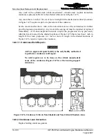
Using a feeler gauge, check the side clearance between the retainers and rocker arms;
the side clearance must be 0.002 - 0.015 inches; refer to Figure 10-72.
Figure 10-72.
Rocker Arm Side Clearance
7.
Torque the screws (Figure 10-59) (20) per Appendix B.
8.
Measure the exhaust rocker arm-to-rotocoil clearance; refer to Figure 10-73. If the
clearance exceeds 0.200 inches, replace the pushrods with authorized over sized
pushrods (P030) if the dry lash exceeds the limit.
Figure 10-73.
Rocker Arm-to-Rotocoil Clearance
9.
Measure the dry valve gear lash at valve tip-to-rocker foot with the piston at top dead
center and compare with limits in Section 10-8.5. Replace the pushrods with
authorized over sized pushrods (P030) if the dry lash exceeds the limit.

