Non-Overhaul Removal and Replacement
Teledyne Continental Motors, Inc.
TM
10-98
IOF-550 Permold Series Engine Maintenance Manual
1 April 2007
10.
Install a new rocker cover gasket (28) (with the beaded side of the gasket toward the
rocker cover) and the rocker cover (29); secure with screws (32), new lock washers
(31) and washers; torque the rocker cover screws (32) to Appendix B specifications.
10-8.14. IOF-550-N, P & R Valve Mechanism and Pushrod Installation
Procedure
1.
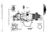
With the engine upright, lubricate the pushrods (40) (Figure 10-61) with clean 50-
weight aviation engine oil and install the pushrods through the cylinder openings into
the pushrod housings (35).
2.
Before installing the valve actuating parts on each cylinder, turn the crankshaft until
the pushrods are at their lowest position in the cylinder.
3.
Lubricate the rocker arms (20), new thrust washers (23) and new valve rocker shafts
(24) with clean 50-weight aviation engine oil.
4.
Slide the shaft (24) into the rocker arm assembly.
5.
Install the new thrust washer (23) on each end of the rocker shaft.
6.
Install the rocker and shaft assemblies on the rocker arm boss with retainers (25), new
tab washers (26) and screws (27).
7.
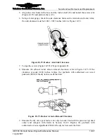
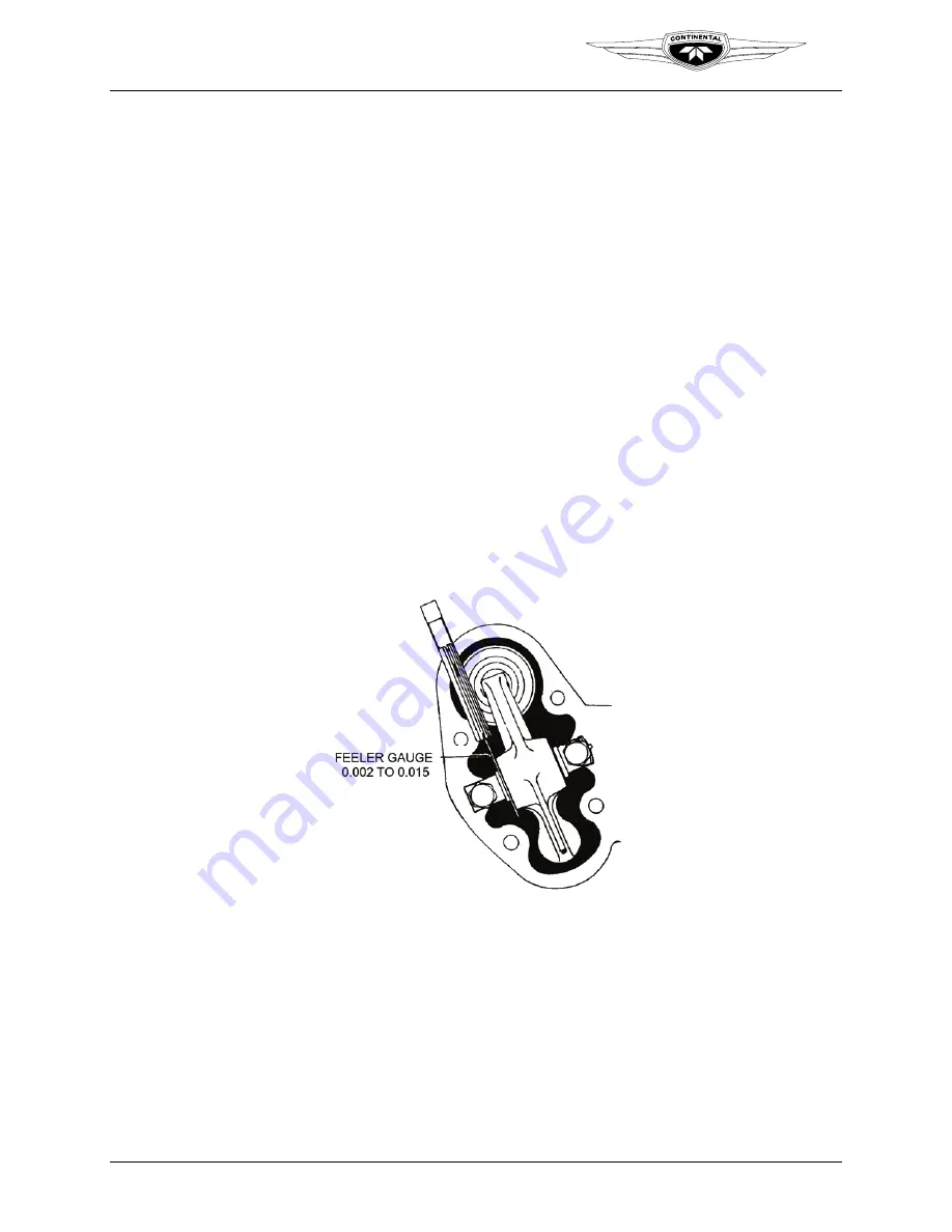
Using a feeler gauge, check the side clearance between the retainers and rocker arms;
the side clearance must be 0.002 - 0.015 inches; refer to Figure 10-74.
Figure 10-74.
Rocker Arm Side Clearance
8.
Torque the screws (27) (Figure 10-61) per Appendix B.
9.
Measure the exhaust rocker arm-to-rotocoil clearance; refer to Figure 10-75. If the
clearance exceeds 0.200 inches, replace the pushrods with authorized over sized
pushrods (P030) if the dry lash exceeds the limit.


