Teledyne Continental Motors, Inc.
TM
Engine
Description
IOF-550 Permold Series Engine Maintenance Manual
2-29
1 April 2007
2-2.10. Induction System
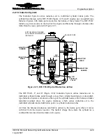
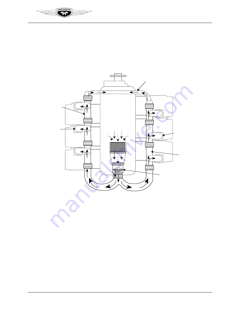
The Induction System carries induction air to individual cylinder intake ports. The
cylinder head design on the IOF-550-B (Figure 2-23) and C engines uses an updraft-type
Induction System with intake ports located on the bottom of the cylinder. The IOF-550-C
induction system mounts on the back of the engine and branches through a balance tube
rather than the top as pictured in Figure 2-23.
RISER
CYL NO.
3
RISER
CYL NO.
5
RISER
CYL NO.
1
RISER
CYL NO.
4
RISER
CYL NO.
6
RISER
CYL NO.
2
BOTTOM VIEW OF ENGINE
WITH INDUCTION MANIFOLD
INSTALLED
BALANCE TUBE
INDUCTION
RISER
AIR
FILTER
AIR
THROTTLE
VALVE
INDUCTION
RUNNER
INDUCTION
RISER
INDUCTION
RUNNER
Figure 2-23.
IOF-550-B Updraft Induction Airflow
The IOF-550-N, P, and R (Figure 2-24) Induction System carries induction air to
individual cylinder intake ports through a cross flow cylinder head design. A downdraft-
type Induction System is mounted on the top of the cylinder heads, with a balanced intake
manifold mounted above the engine crankcase which carries induction air to the
individual cylinder intake distribution ports via cylinder induction tubes.
Air from the balanced induction manifold is carried to the intake ports where it mixes
with fuel from the injector nozzles. The fuel/air charge then enters the cylinder as a
combustible mixture when the intake valve opens.


