Application manual for YRB-4EML-31S safety relay
Contrinex AG Industrial Electronics
32
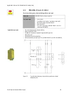
Function description
Start
Action
Result
Diagnostics
1. Close the safety door.
The safety door circuit closes enable circuit S11, S12 and
S11, S22 of the safety relay.
The circuit is enabled via the reset button.
Power
K1
K2
2. Press reset button S2.
Contactors K3 and K4 are activated and the mirror contacts
(N/C contacts of K3 and K4) in the reset circuit are opened.
Power
K1
K2
Stop
Action
Result
Diagnostics
1. Open the safety door.
The safety function is triggered and contactors K3 and K4
are opened.
In the reset circuit, the mirror contacts of K3 and K4 are
closed.
Power
K1
K2
Notes on the application
example
1. The connecting cables for the position switches in the sensor circuit (safety door
switch) should either be laid separately or protected against mechanical damage.
2. The position switch is positive opening according to EN 60947-5-1.
3. Contactors K3 and K4 have mirror contacts according to EN 60947-4-1.
4. Stop category 0 describes an immediate stop by removal of power by interrupting a
machine or drive element according to EN 60204.
5. When using the safety relay, take into consideration the maximum permissible number
of cycles for observing the SIL/PL safety characteristics in the specific application. The
safety characteristics can be found in the FUNCTIONAL SAFETY
CHARACTERISTICS data sheet or the SISTEMA library.

