background image

Application manual for YRB-4EML-31S safety relay 

Contrinex AG Industrial Electronics 


Table of contents 


1  

Introduction ..................................................................................................................................................... 7 

1.1  

Target group for this application manual ................................................................................................ 7 

2  

Safety of machines and systems ..................................................................................................................... 9 

2.1  

Functional safety ................................................................................................................................... 10 

2.2  

Practical procedure according to EN ISO 13849 ................................................................................... 10 

2.2.1  

Definition of the safety function ................................................................................................... 10 

2.2.2  

Determination of the required performance level (PLr) .............................................................. 11 

2.2.3  

Technical implementation ............................................................................................................. 11 

2.2.4        Dividing the safety function into subsystems ................................................................................ 12 

2.2.5  

Determination of the achieved PL for each subsystem ................................................................. 12 

2.2.6  

Determination of the achieved PL for the overall safety function ................................................ 14 

2.2.7  

Verification of the achieved PL ...................................................................................................... 14 

2.2.8  

Validation ...................................................................................................................................... 14 

2.3  

Practical procedure according to EN ISO 62061 ................................................................................... 15 

2.3.1  

Specification of requirements for the safety-related control function (SRCF) ............................... 15 

2.3.2  

Determination of the required safety integrity level (SIL) ............................................................ 15 

2.3.3  

Drafting the safety-related electrical control system ................................................................... 15 

(SRECS) .......................................................................................................................................................... 15 

2.3.4 

Determination of the achieved safety integrity for the entire SRECS ........................................... 16 

2.3.5        Verification of the achieved SIL ...................................................................................................... 16 

2.3.6  

Validation ...................................................................................................................................... 17 

3  

Safety technology basics ............................................................................................................................... 18 

3.1  

Cross-circuit detection .......................................................................................................................... 18 

3.2  

Maximum cable lengths ........................................................................................................................ 19 

3.3  

Stop ....................................................................................................................................................... 20 

4  

Application examples for YRB-4EML-31S safety relay .................................................................................. 22 

4.1  

Emergency stop ..................................................................................................................................... 22 

4.1.1  

YRB-4EML-31S up to PL c/SIL 1 ...................................................................................................... 23 

4.1.2  

YRB-4EML-31S up to PL d/SIL 2 ..................................................................................................... 25 

4.2  

Light curtain (ESPE) ................................................................................................................................ 27 

Summary of Contents for YRB-4EML-31S

Page 1: ...SAFETY RELAY APPLICATION Application manual for YRB 4EML 31S safety relay ...

Page 2: ...on manual for YRB 4EML 31S safety relay Contrinex AG Industrial Electronics 2 Designation Revision Order No SAFETY RELAY APPLICATION 02 13 07 2016 605 000 728 This manual is valid for YRB 4EML 31S from Contrinex ...

Page 3: ... will result in death or serious injury WARNING This indicates a hazardous situation which if not avoided could result in death or serious injury CAUTION This indicates a hazardous situation which if not avoided could result in minor or moderate injury This symbol together with the signal word NOTE and the accompanying text alert the reader to a situation which may cause damage or malfunction to t...

Page 4: ...ntended use of the products in your specific application in particular with regard to observing the applicable standards and regulations All information made available in the technical data is supplied without any accompanying guarantee whether expressly mentioned implied or tacitly assumed In general the provisions of the current standard Terms and Conditions of Contrinex apply exclusively in par...

Page 5: ... overall safety function 14 2 2 7 Verification of the achieved PL 14 2 2 8 Validation 14 2 3 Practical procedure according to EN ISO 62061 15 2 3 1 Specificationofrequirements forthe safety related control function SRCF 15 2 3 2 Determination of the required safety integrity level SIL 15 2 3 3 Drafting the safety related electrical control system 15 SRECS 15 2 3 4 Determination of the achieved saf...

Page 6: ...rial Electronics 6 4 2 1 YRB 4EML 31S up to PL e SIL 3 28 4 3 Movable guards 30 4 3 1 YRB 4EML 31S up to PL d SIL 2 31 4 6 Contact extension forcibly guided contacts 33 A Appendix for document lists 34 A 1 Explanation of terms 34 A 1 Case studies connection to a PLC 36 ...

Page 7: ...he aim is to eliminate barriers to trade within the EU However even outside the European Economic Area many European standards are gaining in importance due to their international status The fact that the safety of machines and systems not only depends on the components and technologies used but is mainly affected by the human factor is no surprise 1 1 Target group for this application manual This...

Page 8: ...Application manual for YRB 4EML 31S safety relay Contrinex AG Industrial Electronics 8 1 3 Symbols used Emergency stop AOPD light curtain Movable guard ...

Page 9: ...e is one of the most important single market directives It is of such importance because machine construction is one of the industrial mainstays of the European Economic Area The Machinery Directive defines the requirements machinery must meet before it can be placed on the market and operated in the European Economic Area It also contains essential health and safety requirements for the planning ...

Page 10: ...voidance of systematic errors Control of systematic errors Control of random faults or failures The requirements of the safety related parts of a machine control system are specified in EN ISO 13849 and EN 62061 The standard specifies the various safety levels in the form of the performance level and safety integrity level SIL for the safety related parts according to the degree of risk and descri...

Page 11: ... according to EN 13849 1 Meaning of individual parameters S severity of injury S1 Slight normally reversible injury S2 Serious normally irreversible injury F frequency and duration of exposure to the hazard F1 Seldom to not very frequent or exposure to hazard is brief F2 Frequent to continuous or exposure to hazard is long P possibility of avoiding or limiting damage P1 Possible under specific con...

Page 12: ...ning the performance level is the PFHd value the statistical probability of a dangerous failure per hour The safety characteristics can be found in the FUNCTIONAL SAFETY CHARACTERISTICS data sheet or the SISTEMA library The diagram below shows the basic relationship between PL and the safety characteristics category DC and MTTFd PFHD a 5 MTTFd low 10 b MTTFd 10 6 medium c MTTF 7 10 high d 8 10 e C...

Page 13: ...safety function between the tests The loss of the safety function is detected by the test Mainly characterized by the structure 3 The requirements of category B and the use of proven safety principles must be met Safety related parts must be designed so that A single fault in any of these parts does not lead to the loss of the safety function and the single fault is detected whenever this is feasi...

Page 14: ...as proven components and safety principles The systematic aspects include Correct dimensioning of components Consideration of expected operating conditions and ambient conditions Use of basic and proven safety principles Avoidance of specification errors and software errors through testing 2 2 8 Validation The last step should check whether the selected measures achieve the necessary risk reductio...

Page 15: ...er semiconductor pulses are disabled Safe state Power circuit has no power 2 3 2 Determination of the required safety integrity level SIL The required SIL is determined in combination with the safety function within the framework of the higher level risk assessment Effect Severity Class Class Class Class Class S 3 4 5 7 8 10 11 13 14 15 Death loss of an eye or arm Permanent loss of fingers 4 SIL 2...

Page 16: ...g of discrete components this value must be determined using the table below Table 3 Determination of the safety integrity level for a subsystem with discrete components according to EN 62061 Safe failure fraction Hardware fault tolerance 1 0 1 2 60 Not permitted 2 SIL 1 SIL 2 60 to 90 SIL 1 SIL 2 SIL 3 90 to 99 SIL 2 SIL 3 SIL 3 99 SIL 3 SIL 3 SIL 3 1 A hardware fault tolerance of N means that N ...

Page 17: ...d level of conformity of the design of safety related parts of the control system SRP CS within the overall specifications for the safety requirements of the machinery Before validation of the design of the SRP CS or the combination of SRP CS that contains the safety function the specification requirement for the safety function must be confirmed Validation involves performing analysis and functio...

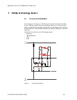
Page 18: ...ten makes it necessary to provide redundancy in the control structure Cross circuit detection has the ability to detect short circuits bridges or short circuits to ground between two channels either immediately or within the framework of cyclic self monitoring A cross circuit may be due to one of the following reasons Squeezing High temperatures Chips Acids L L1 1 2 A1 S11 S12 S21 S22 GND PTC 3 K1...

Page 19: ... Electronics 19 3 2 Maximum cable lengths Depending on the size of the machine or system a considerable amount of cabling may be required to wire the sensors Make sure that the specified cable lengths are not exceeded so as to ensure error free operation of the safety relay ...

Page 20: ...ndently of the operating mode In order to stop a machine three stop categories are defined in EN 60204 1 which describe the stop control sequence independently of an emergency situation Stop category 0 Stopping by immediate removal of power to the machine drives i e an uncontrolled stop Stop Figure 7 Stop category 0 example Stop category 1 A controlled stop with power available to the machine driv...

Page 21: ...lication manual for YRB 4EML 31S safety relay Contrinex AG Industrial Electronics 21 Stop category 2 A controlled stop with power available to the machine drives Stop Brake Figure 9 Stop category 2 example ...

Page 22: ... ISO 13850 In this case the operating mode is not taken into consideration Risk of Electric shock Movement Shutdown with emergency stop Figure 10 Emergency stop Stop with emergency stop The emergency stop function should not be used as a substitute for safety equipment or other safety functions but should be designed as additional safety equipment The emergency stop function must not adversely aff...

Page 23: ...AC DC 3 enabling current paths 1 signaling current path Monitored manual or automatic start Basic insulation Stop category 0 Cat 4 PL e according to EN ISO 13849 1 SIL CL 3 according to EN 62061 Application example Single channel emergency stop monitoring Manual reset S33 S34 Stop category 0 Safety level of the example up to PL c EN ISO 13849 1 and SIL 1 EN 62061 Figure 11 Single channel emergency...

Page 24: ... positive opening according to EN 60947 5 1 2 Stop category 0 describes an immediate stop by removal of power by interrupting a machine or drive element according to EN 60204 3 Proven components and proven safety principles according to EN ISO 13849 2 must be used when applying category 1 4 The occurrence of a fault can lead to the loss of the safety function 5 The connecting cables for the emerge...

Page 25: ...nt path Monitored manual or automatic start Basic insulation Cat 4 PL e according to EN ISO 13849 1 SIL CL 3 according to EN 62061 Application example Two channel emergency stop monitoring Manual reset S33 S34 Feedback of contactor contacts K3 and K4 at S33 and S34 Stop category 0 Monitoring of external contactors Safety level of the example up to PL d EN ISO 13849 1 and SIL 2 EN 62061 Figure 12 T...

Page 26: ...ety function is triggered and contactors K3 and K4 are opened In the reset circuit the mirror contacts of K3 and K4 are closed Power K1 K2 Notes on the application example 1 The emergency stop control device is positive opening according to EN 60947 5 1 2 Contactors K3 and K4 have mirror contacts according to EN 60947 4 1 3 Stop category 0 describes an immediate stop by removal of power by interru...

Page 27: ...he light curtains must be installed in such a way that it is impossible to access the protected field from above below or behind If this is not guaranteed additional safety equipment must be installed The machine control system must be capable of being influenced electrically and permit dangerous states to be exited immediately in each operating phase The ambient conditions must not adversely affe...

Page 28: ...h Monitored manual or automatic start Basic insulation Cat 4 PL e according to EN ISO 13849 1 SIL CL 3 according to EN 62061 Application example Two channel light curtain monitoring Cross circuit detection via the light curtain Manual reset S33 S34 Feedback of contactor contacts K3 and K4 at S34 Stop category 0 Monitoring of external contactors Safety level of the example up to PL e EN ISO 13849 1...

Page 29: ...bject in the protected field The safety function is triggered by the interruption of the light curtain and contactors K3 and K4 are opened In the reset circuit the mirror contacts of K3 and K4 are closed Power K1 K2 Notes on the application example 1 The light curtain ESPE must meet type 4 requirements from standard EN 61496 1 2 Contactors K3 and K4 have mirror contacts according to EN 60947 4 1 3...

Page 30: ...ed Closing the guard does not automatically initiate the hazardous machine functions Interlocking devices can combine various functions and have a position monitoring function for guards The interlocking device detects whether or not the guard is closed and issues a stop command Some interlocking devices have a guard locking function which locks the guard while the hazardous machine functions are ...

Page 31: ... Monitored manual or automatic start Basic insulation Cat 4 PL e according to EN ISO 13849 1 SIL CL 3 according to EN 62061 Application example Two channel non equivalent safety door monitoring with two position switches Manual reset S33 S34 Feedback of contactor contacts K3 and K4 at S33 and S34 Stop category 0 Monitoring of external contactors Safety level of the example up to PL d EN ISO 13849 ...

Page 32: ...the mirror contacts of K3 and K4 are closed Power K1 K2 Notes on the application example 1 The connecting cables for the position switches in the sensor circuit safety door switch should either be laid separately or protected against mechanical damage 2 The position switch is positive opening according to EN 60947 5 1 3 Contactors K3 and K4 have mirror contacts according to EN 60947 4 1 4 Stop cat...

Page 33: ...t be designed so that none of the mechanically connected N C contacts can close if a N O contact is closed and none of the mechanically connected N O contacts can close if a N C contact is closed These requirements apply for the entire service life of the relay and for reasonably foreseeable failure conditions The effects of reasonably foreseeable breaks and or wear on parts of the elementary rela...

Page 34: ...ons to meet a safety requirement Category Classification of the resistance to faults according to EN ISO 13849 1 Safety integrity level claim limit SIL CL SIL claim limit suitability Probabilityof a dangerous failure per hour PFHd Probability of a dangerous failure per hour Mission time tM Duration of use Probability of failure on demand low demand PFD Probability of failure relative to the number...

Page 35: ...fied in two dimensions AOPD Active optoelectronic protective device Device with a sensor function that is generated by optoelectronic transmit and receive elements which detects the interruption of optical radiation generated in the device by an opaque object located in the specified protective field or for an optical data link on the axis of the light beam In DIN EN 692 mechanical presses DIN EN ...

Page 36: ...e below can work together with PLC 1 red below thus creating a redundant and dependent installation on the PLC side This principle is theoretically based on the same kind of wiring than when an emergency stop button is used However it is also up to the end user to check what will be the final PL or SIL level acquired with this setup The most important is to connect the inputs S11 S12 and S22 toget...

Reviews: