3
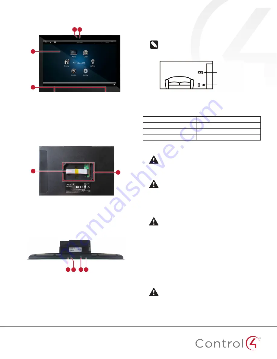
Front view
Figure 1: Front view
C
B
A
D
A
LED
—Indicates when the camera is on.
B
Camera
—For video intercom calls.
C
Display
—7
"
or 10
"
diagonal, capacitive touch screen with
1280 × 800 resolution.
D
Speakers
—Provide stereo audio.
Back view
Figure 2: Back view
A
B
A
Ribbon cable
-
Provides data and power connection to the
touch screen from the power box.
B
Mounting ring
—Fits into the power box.
Top view
Figure 3: Top view (with power box attached)
A
C D
B
A
Unlabeled pinhole button
—Press and hold a straightened
paper clip into this hole, then the RESET hole, to reset the
touch screen to factory defaults. Make sure you use the hole
to the
left
of the microphone.
B
Microphone
—Records audio.
C
RESET
pinhole button—Press after pressing the other pinhole
to reset the touch screen.
D
Power button
—Press to turn off the touch screen, or press and
hold to reboot.
Touch screen placement
Place the touch screen in a convenient location at eye level,
typically near the entrance of the room, approximately 57 to 61
inches (145 cm to 155 cm) from the floor (Figure 3).
Note:
Consider the camera on the panel and the height
of the people in the home who will use the camera for
Video Intercom.
Figure 3: Touch screen placement
LED indicator
The LED on the touch screen indicates the camera status of the
camera and booting information as described in the next table.
Camera/LED color state
Touch screen status
Off
Camera is off
Green
Camera is on
Green (blinking slowly)
Touch screen is booting
Installation
Warning!
Before installing the touch screen, switch off
the circuit breaker or remove the fuse from the fuse box.
AVERTISSEMENT !
Pour l’endroit où vous installez
l’écran tactile, coupez le disjoncteur ou enlevez le fusible
de la boîte de fusible.
Important!
Before you can complete the instructions
below, you must have a 7
"
or 10
"
Touch Screen wall box
installed according to the documentation provided in
the wall box kit. See “Accessories” for details.
Important !
En coupant l’ouverture pour la boîte de
mur, ne coupez pas l’ouverture trop grande. Soyez
conservateur et agrandissez-avec précaution la comme
nécessaire. Voyez que <<Accessories>>.
Important!
When cutting the opening for the wall box,
do not
cut the opening too large. Be conservative and
cautiously enlarge it as needed.
Important !
En coupant l’ouverture pour la boîte de
mur, ne coupez pas l’ouverture trop grande. Soyez
conservateur et agrandissez-avec précaution la comme
nécessaire.
Power and network installation options
This device uses an Ethernet or WiFi network connection, and
can be powered using PoE or AC power.
Choose one of the following options to install the power and
network communication.
Caution!
Do not attempt to use PoE and AC power at
the same time. Choose only one power option.
ATTENTION !
Ne pas tenter d’utiliser PoE et AC en
même temps. Choisir une seule option d’alimentation.
Touch screen
AC power
(unless using PoE)


