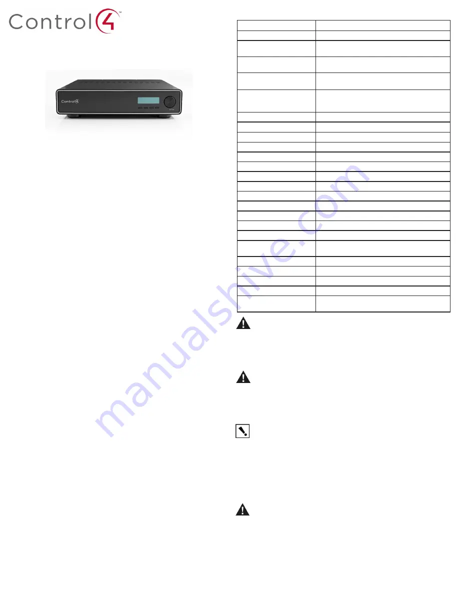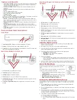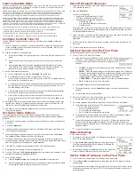
Multi Tuner V2
Installation and Setup Guide
Supported Models
•
C4-TUN2-E-B Multi Tuner V2
• C4-XMOD Optional XM Module (ships separately)
Important Safety Instructions
Box Contents
• Control4 Multi Tuner V2
• AC Power Cable
• Multi Tuner V2 Installation and Setup Guide (this document)
1.
Read and keep these instructions.
2.
Heed all warnings and follow all instructions for this product in this and other Con-
trol4® documents included with or related to this product.
3.
Improper use of this product may result in potential electric shock.
4.
Do not use this product near water.
5.
Never spill liquid of any kind on this product.
6.
Clean this product only with a damp or dry cloth. Do not use liquid cleaners or aerosol
cleaners to clean the product.
7.
Install this product according to the manufacturer’s instructions.
8.
Install this product according to the National Electrical Code ANSI/NFPA 70 and the
prevailing local codes and requirements.
9.
This product is designed for IT power systems with phase-to-phase voltage 120V,
240V, or 277V.
10. This product should be operated with the type of power indicated on the marked label.
If you are not sure of the type of power available, consult your Control4 dealer or local
power company.
11. Slots and openings on a cabinet rack, and components used with this product are pro-
vided for ventilation, reliable operation, and protection from overheating of the product.
These slots and openings must not be blocked or covered.
12. This product should never be placed near or over a radiator or heat register, or in a
built-in installation unless proper ventilation is provided.
13. Never push objects of any kind into this product through cabinet slots because they
may touch dangerous voltage points or short out parts that could result in a fire or
electric shock.
14. Only use the attachments and accessories included with this product or recommended
by Control4.
15. Do not allow anything to rest on the power cord. Do not install or place this product
where people will walk on the cord.
16. Do not use extension cords with any products in a Control4 system.
17. If applicable, unplug this product during lightning storms or when unused for long
periods of time.
18. This product must be installed by qualified professionals only.
19. Do not attempt to service this product yourself except as noted in this guide. Opening
or removing covers of internal components may expose you to dangerous voltage
points or other risks.
20. Refer all servicing to qualified service personnel. Servicing is required when the ap-
paratus has been damaged or frayed in any way; for example, a power-supply cord or
plug is damaged, liquid has been spilled or objects have fallen into this product, this
product has been exposed to rain or moisture, this product does not operate normally,
or this product has been dropped.
Front Display (LCD)
—Displays current tuner settings and LCD menus.
Buttons
—Provides access to menu options displayed on the LCD.
Select Dial
—Scroll through list items and options displayed on the LCD or make selec-
tions. Also used during setup to ID device.
1
2
3
Feature
Description
Tuners
Two independent AM/FM tuners. One expansion slot.
AM Antenna Input
300 Ohm twin-lead spring terminals for stripped wire.
Antenna shared between Tuners 1 and 2.
FM Antenna Input
75 Ohm coax female “F” connector. Antenna shared
between Tuners 1 and 2.
XM Antenna Input (available
with C4-XMOD model only)
XM Antenna Input. XM Radio has been granted Part II
type approval for this receiver.
Outputs
L/R line-level Audio Output on RCA connectors per
tuner.
SPDIF Digital Coax per tuner.
FM Performance
Tuning Range
76.0 MHz - 108.0 MHz
Sensitivity (50 ohm)
2.2 mV EMF
AM Suppression
50 dB
Audio Stereo Separation
25 dB
Audio THD (1 Khz)
< 0.5%
AM Performance
Tuning Range
149 – 23000 Khz
Sensitivity
38 mV EMF
Audio S/N
56 dB
Audio THD (1 Khz)
< 0.5%
THD (1 kHz)
0.7 %
SIgnal-to-Noise Ratio
50 dB
XM Performance
(C4-XMOD
only)
Depends on XM subscription and your area.
Display
4-line LED backlit LCD
Communications
IEEE 802.3 10/100 Ethernet, RJ-45 jack
Power Requirements
115/230 VAC, 60/50 Hz, 5 Watt Maximum, 0.05A
Dimensions
H x W x D: 3.5” x 17.0” x 15.9” (89 x 432 x 404 mm)
Weight: C4-TUN2-E-B (with 2
AM/FM tuners only)
Weight: 9.9 lbs. (4.50 kg)
Shipping Weight: 13.75 lbs. (6.25 kg)
Product Specifications
WARNING!
Do not expose the apparatus to dripping or splashing. Do not place
objects filled with liquids near the apparatus.
AVERTISSEMENT !
N’exposez pas l’appareil à l’égoutture ou à l’éclaboussement. Ne
placez pas les objets remplis de liquides près de l’appareil.
WARNING!
Setzen Sie den Apparat nicht Bratenfett oder dem Spritzen aus. Setzen
Sie nicht die Gegenstände, die mit Flüssigkeiten nahe dem Apparat gefüllt werden.
WARNING!
To reduce the risk of fire or electrical shock, do not expose this apparatus
to rain or moisture.
AVERTISSEMENT !
Pour réduire le risque du feu ou de choc électrique, n’exposez
pas cet appareil à la pluie ou à l’humidité.
WARNING!
Um die Gefahr des Feuers oder des elektrischen Schlages zu verringern,
setzen Sie diesen Apparat nicht Regen oder Feuchtigkeit aus.
IMPORTANT!
Using this product in a manner other than outlined in this document
voids your warranty. Further, Control4 is NOT liable for any damage incurred with the
misuse of this product. See “Limited 2 Year Warranty.”
IMPORTANT !
Employer ce produit en quelque sorte autre que décrit dans ce docu-
ment vide votre garantie. De plus, Control4 n’est pas responsable d’aucun dommage
encouru avec l’abus de ce produit. Voyez que « a limité la garantie de 2 ans. »
WICHTIG!
Das Verwenden dieses Produktes in gewissem Sinne anders als umrissen
in diesem Dokument hebt Ihre Garantie auf. Weiter ist Control4 NICHT für irgendeine
Beschädigung verantwortlich, die mit der Fehlanwendung dieses Produktes genom-
men wird. Sehen Sie, daß „begrenzte eine 2 Jahr-Garantie.“
WARNING!
This CLASS I apparatus must be connected to an AC mains socket outlet
that has a protective earthing connection (i.e., third-prong ground conductor). DO NOT
DEFEAT THE PROTECTIVE EARTHING CONNECTION!
AVERTISSEMENT !
Cet appareillage de la CLASSE I doit être relié à une sortie de
douille de forces à C.A. qui a un raccordement de mise à la terre protecteur (c.-à-d.,
conducteur rectifié parfourche). NE DÉFAITES PAS LE RACCORDEMENT DE MISE
À LA TERRE PROTECTEUR!
WARNING!
Dieser Apparat der KATEGORIE I muss an einen Wechselstrom-
Hauptleitungseinfaßungsanschluß angeschlossen werden, der einen schützenden
Erdunganschluß hat (d.h., Drittzinke geriebenen Leiter). BESIEGEN SIE NICHT DEN
SCHÜTZENDEN ERDUNG-ANSCHLUSS!
Front and Rear Panel Descriptions
Front Panel
Back Panel (Model C4-TUN2-E_B)
6
AC Power Inlet
—for supplied power cord only.
FM Antenna port
—for FM radio reception.
AM Antenna port
—for AM radio reception.
Ethernet port
—RJ-45 for a 10/100 BaseT Ethernet connection.
AM/FM Audio Out ports
—RCA style Left and Right line-level analog audio out to con-
nect to an audio amplifier.
SPDIF Coax Digital Audio Out ports
—for digital audio out to connect to an audio
amplifier.
1
2
3
4
5
6
Install the Multi Tuner V2
Plan your Audio Out connections: You can connect to up to three amplifiers, audio
switches, or receivers/pre-amp.
Set the Multi Tuner V2 in an A/V rack or another installation location.
Connect the Multi Tuner V2 audio outputs: Connect to your amplifier, audio switch, or
receiver audio inputs using audio cables.
Connect the antennas required to support the connected output devices.
• AM Antenna
: AM loop antenna
• FM Antenna
: F-type coaxial, 75 ohm impedance
• XM Antenna
: XM antenna
Connect to the Network:
• Ethernet: Plug the data cable from the home network connection into the Multi
Tuner V2 RJ-45 port (labeled “Ethernet”) and the network port on your wall or at
the network switch.
Connect to Power: The power cord provided to the back of the Multi Tuner V2 and to
the power outlet. Once the power cord is connected, the Multi Tuner V2 will power up.
1
2
3
4
5
6
Use the
Select Dial
to tune the XM tuner to channel 0 and record the XM Radio ID
(SDARS ID) that displays in the LCD window.
Contact XM Satellite Radio Inc. to subscribe to the XM radio service (see the next sec-
tion for details).
1
2
Home Network Requirements
Ensure that your home network solution is in place before starting your system setup. The
multi tuner can be controlled through Ethernet.
Antenna Requirements:
• Ensure that a proper AM/FM antenna is installed before beginning your system setup.
• For XM systems, install the XM antenna before beginning your system setup.
Features and Benefits
• Triple tuning capability
—Sends out up to three audio signals, including two AM/FM
signals and an optional XM® satellite radio signal. An XM antenna is supplied and
required with the optional XM module.
• Multi zone versatility
—Handles a family’s radio needs simultaneously with one
component.
• XM option available
—Subscribes to 150+ channels of satellite radio. Features
include:
• Over 150 channels coast-to-coast
• All music channels 100 percent commercial-free
• Music, news, talk, sports and entertainment
• Digital quality audio
• Many commercial-free channels
XM requires a monthly subscription from XM Satellite Radio. To subscribe, contact XM at
www.xmradio.com or at 1-800-XMRADIO (800-967-2346).
• Data rich
—Incorporates RDS support for FM, the Multi Tuner V2 can display any
station-specific or media-specific information supported by the radio station, such as
station name, artist name, or song title.
• Compact rack size
—Rack-mountable component integrates easily with other audio
equipment.
• Control4 network integration
—Provides immediate control and easy updates
through supported user interfaces (Control4 keypads, touch screens, and on-screen
menus).
• Single point of control
—Controls up to three separate radio streams using one
simple LCD interface.
1 2 3
1 2 3 4
5
Back Panel (Model C4-TUN2-E_B with C4-XMOD Option
Installed)
6
AC Power Inlet
—for supplied power cord only.
FM Antenna port
—for FM radio reception.
AM Antenna port
—for AM radio reception.
Ethernet port
—RJ-45 for a 10/100 BaseT Ethernet connection.
AM/FM Audio Out ports
—RCA style Left and Right line-level analog audio out to con-
nect to an audio amplifier.
SPDIF Coax Digital Audio Out ports
—for digital audio out to connect to an audio
amplifier.
XM Antenna port
—for XM satellite radio reception.
XM Audio Out ports
—RCA style for left and right analog line-level out for connection to
an audio amplifier.
XM SPDIF Coax Digital Audio Output
.
1
2
3
4
5
6
7
8
9
1 2 3 4
5 7 8 9
About the Main Menu
When you first power up the Multi Tuner V2, the following System
Status screen appears momentarily (similar to the one on the
right).
The System Status screen is then replaced by the Multi Tuner V2
main menu (shown in the screen to the right).
• Tun1
—Choose this to manually change a setting on Tuner
1, an AM/FM Tuner.
• Tun2
—Choose this to manually change a setting on Tuner
2, an AM/FM Tuner.
• XM
—Displays only when C4-XMOD is used. Choose this to
manually change a setting on the XM Tuner.
• Setup
—Choose this to access the Settings menu.
Activate the XM Satellite Radio Service
Tuners upgraded with the XM Module Kit require a monthly subscription to the XM Satel-
lite Radio service in order to receive XM radio channels. To subscribe and activate these
services:
When instructed to do so by XM Satellite Radio Inc., tune the XM tuner to Channel 1
for about 20 minutes. When the tuner begins receiving XM stations, the LCD screen is
enriched with station-specific information.
If the XM tuner is not receiving XM stations after 20 minutes:
3
4
Move your antenna to a new location.
Go to http://www.xmradio.com/refresh/
Tune to Channel 1 again and wait approximately 20 minutes for the LCD screen to
refresh.
a
b
c


