background image

Summary of Contents for CDC 721

Page 1: ...I J 1 CONT OL DATA I r J CO O TION CDC 721 ENHANCED DISPLAY TERMINAL 62950101 OPERATOR S GUIDE INSTALLATION INSTRUCTIONS ...

Page 2: ...I I I I I I I I I I I I I t I I P u b l i c a t i o n N o I I I I 62950101 I REVISION LETTERS I 0 Q AND X ARE NOT USED 1983 by Control Data Corporation Printed in the United States of Arnerica ii Address comments concerning this manual to Control Data Corporation Publications and Graphics Div 2401 North Fairview Avenue St Paul Minnesota 55113 or use Comment Sheet in the back of this manual ...

Page 3: ...he page number if the entire page is affected A bar by the page number indicates pagination rather than content has changed PAGE I REV PAGE I REV PAGE IREV Front Cover Title Page WARNING ii thru xvi A 1 1 thru 1 6 A 2 1 thru 2 10 A 3 1 thru 3 12 A 4 1 thru 4 21 A 5 1 A 6 1 thru 6 23 A A I thru A 37 A B 1 thru B 19 A Comment Sheet A Mailer Back Cover 62950101 iii iv ...

Page 4: ......

Page 5: ... how to operate the terminal in CYBER mode That mode is for operations with CDC CYBER computer systems such as those of the 120 or 170 series This is accompanied with general information such as A general description of the terminal A description of operator controls and indicators How to start up the terminal and run its self tests Instructions on cleaning the terminal Error recovery and fault is...

Page 6: ... applicable to enhanced production model terminals only 721 220 Graphics Board Hardware Installation Instructions applicable to enhanced production model terminals only ASSOCIATED MANUALS FOR ORIGINAL MODEL TERMINALS 721 Display Terminal Operator s Guide Installation Instructions 721 Display Terminal Unpacking Packing Instructions 721 Display Terminal Reference Manual All manuals may be ordered fr...

Page 7: ...anced firmware option installed If you have a CC634 A or CC638 A terminal that does not have that option you should not use this manual Instead you should use the operator s guide installation instruc tions manual that is listed in the preface for the original model terminals CC634 A or CC634 B which has no factory installed optional features CC638 A or CC638 B which has optional graphics board an...

Page 8: ...S 9 10 0 0 6 6 Q Q MODE 2 F CON FIG F CON FIG F CON FIG F CON FIG FOP R D F F A D I A L F A D I A L F DF PLATO T R F A C C E S S 2 100 100 3 4 Q 2 2 _Q 2 2 2 2 2 _ 5 0 6 o 0 0 0 0 0 6 C 2 4 7 8 9 o 0 0 0 0 0 0 0 0 0 0 0 08 6 6 10 __ _ _ _ _ o 0 0 0 MODE 3 F CON FIG F CON FIG F CON FIG F CON FIG FOP R D F F A D I A L F A D I A L F OF T R F Ace E S S 2 3 _ _____ 4 1 0 0 1 0 000 100 o 0 000 0 MODE 4 ...

Page 9: ...el ist mit einem Schutzkontaktstecker versehen Auf richtige Netzspannung ist zu achten da im anderen FaIle das Gerat zerstort wird Die Netzwandsteckdose ist unmittelbar und leicht zuganglich in der Nahe des Gerates zu montieren Netzschalter Der Netzschalter befindet sich an der Frontseite Stellung gedrUckt 0 AUS Stellung gedrUckt I AN Der Geratesicherungsautomat an der RUckseite ist durch Eindruck...

Page 10: ...ziertem Fachpersonal nach Abschalten der Stromzufuhr zum Ger t vorzunehmen Beachten Sie die Wartungs und Garantiebestimmungen Umgebungstemperatur Temperaturwechsel 10 C innerhalb 1 Stunde Relative Feuchtigkeit 20 bis 80 Gewicht inkl Keyboard 21 8 kg Weitere Informationen entnehrnern Sie dem Ger te Manual CDC Nr 62 95 01 01 x 62950101 ...

Page 11: ... Positioning Adjustments 2 9 3 STARTUP AND SELF TESTS Starting Up Terminal Running Self Tests Operator Intervention Test Cyber Mode Test 3 1 3 6 3 6 3 10 3 10 3 10 3 10 3 11 Host Initiated CYBER Mode Test Locally Initiated CYBER Mode Test Installing Memory Module Replacing Battery 4 OPERATING IN CYBER MODE Operator Parameters 4 1 Protected Screen Positions 4 5 Normal Protection Mode 4 6 Automatic ...

Page 12: ...ATION AND CHECKOUT Installation Considerations Required Tools and Supplies Terminal Preparation Board Installation in I F I through I F 3 Cable Installation A I A 2 A 2 A 4 Initial Power On A 5 A S Parameter Entries Checkout CRT Realignment without Touchpanel Installed CRT Realignment with Touchpane1 Installed A 9 A 2S A 32 A 35 B 1200 1200 BAUD INTERNAL MODEM xii General Description B 1 Opera tio...

Page 13: ...board with Spanish Keycap Option 2 10 Optional Touchpane1 2 11 Positioning Adjustments 3 STARTUP AND SELF TESTS Checking TEST Switches Failure Messages for Power On Test Mode Menu 2 1 2 3 2 5 2 6 2 6 2 6 2 7 2 7 2 7 2 9 2 10 3 2 3 3 3 4 3 1 3 2 3 3 3 4 3 5 3 6 3 7 Operator Intervention Test Display 3 7 Key Values Shown During Test Installing a Memory Module Replacing Battery 4 OPERATING IN CYBER M...

Page 14: ...meters 6 Sheets A 12 Mode Installation Parameters 9 Sheets A 19 Estimating Required Realignment A 33 Realignment Entries A 34 Display Alignment Pattern for Use with Touchpanel A 37 B 1200 1200 BAUD INTERNAL MODEM B 1 View of Terminal Showing I F 4 Slot B 1 B 2 Auto dialing Display Messages B 6 B 3 Telephone Line Extension Cord with Duplex Jack Plug B ll B 4 Installing a Modem Equipped Terminal B 1...

Page 15: ...19 6 ERROR RECOVERY FAULT ISOLATION 6 1 Power Problems 6 2 6 2 Power On Test Problems 6 3 6 3 Host Loading Problems 6 4 6 4 Memory Module Loading Problems 6 6 6 5 Operator Intervention Test Problems 6 7 6 6 Display Problems 6 10 6 7 Keyboard and Touchpane1 Problems 6 14 6 8 Printing Problems 6 16 A INSTALLATION AND CHECKOUT A I Problems Possibly Caused by Improper Parameters A 29 62950101 xv xvi ...

Page 16: ......

Page 17: ...satile input output device that may be configured in a communications network be connected via telephone line to a remote computer or be cabled directly to a local computer The terminal may also be locally configured with a character printer or graphics printer The data displayed by the terminal can be in the form of alphanumeric characters domestic or foreign and or graphic symbols or drawings Fi...

Page 18: ...ation facilities at the site The parameters stored in nonvolatile memory can be changed if necessary but only by qualified personnel such as the personnel who install the terminal Certain parameters however can be temporarily changed without making changes to nonvolatile memory These temporary changes may be made by either the operator or the host after the terminal has been placed in the operatin...

Page 19: ...ting mode programs may occur from a memory module or from a host that uses ASCII communications such as the Control Data Shared Network 64K of random access memory RAM for loading and operating memory Parameter selection made via keyboard with parameter storage in nonvolatile memory Asynchronous RS 232 C CCITT V 24 host interface with selectable receive transmit speeds up to 19 200 bps 120 V ac 60...

Page 20: ...symbols Spanish symbols Swedish Finnish symbols or Danish Norwegian symbols with a CC634 B or CC638 B terminal all options are user installed except the touchpanel which must be installed at a CDC repair service center A number such as CC634 B or CC638 B identifies the type of terminal you have and appears on a label at the rear of the terminal with a CC634 A or CC638 A terminal all options are us...

Page 21: ...board are shown in figure 1 2 The terminal weighs 19 5 kg 43 lb and the key board weighs 2 3 kg 5 lb OPERATOR SUPPLIES The only operator supply item required is a replacement for the terminal battery When the terminal is turned off this battery keeps installation parameters stored in memory The terminal automatically checks the voltage of the battery following each power on or reset and displays a...

Page 22: ...1 6 440mm 17 33 in 2 Figure 1 2 Terminal Dimensions 04212 62950101 ...

Page 23: ...ioning adjustments CONTROLS Figure 2 1 shows the location of the terminal controls and table 2 1 defines their function POWER SWITCH RESET SWITCH CONTRAST CON TROL BRIGHTNESS CONTROL LINE VOLTAGE SWITCH o c J LINE VOLTAGE i 5 o I F4 lJel 0 J U TEST NORMAL SWITCH THAT MAY BE ON o o 0 0 OPTIONAL SOARDS IN I F It I F 2t OR I F 3 00 0 I I I IS _____ I O l ilo ol TEST SWITCH oms I CSI CIRCUIT BREAKER 0...

Page 24: ...uit Breaker Rotating control clockwise increases bright ness counterclockwise decreases brightness Allows cormnunication and keyboard support circuits to be tested offline This is described under Operator Intervention Test in section 3 For normal operation switch must be pushed in Used with above described TEST switch to check communication circuits in operator intervention test Conditions termina...

Page 25: ...erminal self tests or in the loading of the operating mode program correc tive actions are described in section 6 Dependent on host Keyboard is locked to prevent input This occurs when A page print operation is done in CYBER mode A block of data is being transmitted in CYBER mode Host commands that keyboard be locked Terminal is unable to transmit data because modem is not ready The output buffer ...

Page 26: ...ed during parameter selection or during startup When instructed by host If enabled by parameters when keyboard entries advance the cursor to the eighth position from end of line or advance the cursor into the last line Whether the alarm sounds loud or soft depends upon parameter selection The only exception to this is when the alarm alternately sounds soft and loud for the first listed condition I...

Page 27: ...with standard key aps figure 2 3 Keyboard with United Kingdom keycap option figure 2 4 Keyboard with French keycap option figure 2 5 Keyboard with German keycap option figure 2 6 Keyboard with Swedish Finnish keycap option figure 2 7 Keyboard with Danish Norwegian keycap option figure 2 8 Keyboard with Spanish keycap option figure 2 9 8888GB 8f9 f3Ej FI F2 F3 F4 F5 F6 F7 Fe F9 FlO FII FI2 FI4 Hr V...

Page 28: ...eycap Option FI F2 F3 F4 F5 F6 F7 F8 F9 FlO FII FI2 FI3 FII 15 NOTES OPTIONAL KEYCAPS ARE SHADED FOR ILLUSTRATING PURPOSES 03942 18 Figure 2 5 Keyboard with French Keycap Option FI F2 F3 F4 F5 F6 F7 F8 F9 FlO FII FI2 FI3 FI4 15 NOTES OPTIONAL KEYCAPS ARE SHADED FOR IU USTRATING PURPOSES 9 l2 27 Figure 2 6 Keyboard with German Keycap Option 2 6 62950101 ...

Page 29: ...5 F6 F7 F8 F9 FlO FII FI2 NOTES OPTIONAL KEYCAPS ARE SHADED FOR ILLUSTRATING PURPOSES FI3 FI4 1 15 t fYc1 DD 03942 29 Figure 2 8 Keyboard with Danish Norwegian Keycap Option lj j 8B8888 B t3 3 E FI F2 F3 F4 F5 F6 F7 F8 F9 FlO FII FI2 NOTES OPTIONAL KEYCAPS ARE SHADED FOR ILLUSTRATING PURPOSES FI3 FI4 FI5 p CLEAR EOL t fYc1 o Figure 2 9 Keyboard with Spanish Keycap Option 62950101 M REL BFl K 03942...

Page 30: ...repeat rate is 15 characters per second In operating modes that use control codes an command sequences the CTRL Control key is used in conjunction with other keys to modify their function and code output There are two Shift ft keys one on each side of the main key cluster The Lock key indicator can be conditioned through parameters to function as a normal shift lock or to limit only alphabetical c...

Page 31: ...mmon use of the touchpane1 is the input of an item choosen from a number of items appearing on the screen This is done by touching the area where the choosen item appears MATRIX LINES IN TOUCHPANEL ARE NEARLY INVISIBLE AND ARE EXAGGERATED HERE FOR ILLUSTRATING PURPOSES Figure 2 10 Optional Touchpanel POSITIONING ADJUSTMENTS Figure 2 11 shows the positioning adjustments available on the terminal an...

Page 32: ...Figure 2 11 Positioning Adjustments 2 10 62950101 ...

Page 33: ...r go through the process with you 1 Check that All cables between terminal and other equipment are securely connected Power cords for equipment are plugged into proper electrical outlets TEST switches shown in figure 3 1 are set for normal operation 2 If program loading is required from a memory module that has not been installed yet install module per instructions near end of this section This is...

Page 34: ...cabled directly to a computer the power on sequence in the next step has to be done in conjunction with the power on sequence for the computer 04062 4 3 Turn on peripherals connected to terminal Then turn on terminal and any connected communications equipment for terminal press the side of POWER switch marked with the 1 With power applied the terminal automatically does a power on self test This t...

Page 35: ...D LOOPBACK FAIL PLACE TEST NORMAL SWITCH TEST SWITCH ENABLED ON INTERFACE BOARD IN DISREGARD INTERNAL MODEM CHECKSUM FAIL IN I F 1 2 OR 3 SLOT I INTERNAL MODEM UART FAIL TO NORMAL POSITION INTERNAL MODEM LOOPBACK FAIL REFER TO MANUAL INTERNAL MODEM REV X X __________ COVERING MEMORY SERIAL FOR TEST SWITCH ENABLED MODULE RESERVED FOR DIAGNOSTIC MEMORY MODULE MESSAGES I RES REV X X NORMALLY SHOWN CO...

Page 36: ...m sounds and FAILURE LOADING MODE appears the mode chosen is either invalid or disabled or a loading problem has occurred Find out the correct mode and repeat step b d If ENTER ACCESS CODE appears enter the assigned four digit code through keyboard As each digit is entered an X replaces one of the four segments in the inverse video block that follows the prompt If code is entered wrong SORRY is di...

Page 37: ...uires the following actions a Dial phone number of host manually b When answer tone is heard switch telephone line to terminal Depending on the arrangement this may be accomplished by pulling up an exclusion key on the phone pressing a DATA button on the phone placing the phone handset on an acoustic coupler if using an external modern or simply hanging up the phone if using the internal modem in ...

Page 38: ...ey twice If keyboard locks press the M REL BREAK key to unlock keyboard and retry If not in CYBER mode and terminal is conditioned for manual selection of operating mode press RESET switch menu appears after power on test If not in CYBER mode and terminal is conditioned for automatic selection of operating mode pullout TEST switch at rear of terminal then press RESET switch This shows a TEST SWITC...

Page 39: ...e your supervisor realign crt per appendix A Each front panel indicator momentarily lights This lighting sequentially goes from left to right and continues throughout the test 3 To check the keyboard do the following a Hold a key down and look at the two digit hexadecimal code that appears on the screen after the words KEYBOARD TEST b Refer to figure 3 5 and compare the displayed code with the val...

Page 40: ...ts at rear of terminal place switch in TEST position c Pullout TEST switch at rear of terminal This disables keyboard input and begins internal cycling of test data If applicable this is accompanied by a communications exchange with the connected parallel interface graphics printer The results of these activities appear on the screen as follows KBD CLOCK OK FAIL if error occurs If a parallel inter...

Page 41: ...8 72 F2 93 1D 9D 19 31 B1 59 7A FA 94 16 96 20 39 B9 60 67 E7 95 1E 9E 21 41 C1 61 14 94 96 26 A6 22 49 C9 62 1C 9C 97 17 97 23 51 D1 63 24 A4 98 1F 9F 24 59 D9 64 2C AC 99 27 A7 25 61 E1 65 34 B4 100 4F CF 26 69 E9 66 3C BC 101 47 C7 27 71 F1 67 44 C4 102 3F BF 28 79 F9 68 4C CC 103 4E CE 29 7E FE 69 54 D4 104 46 C6 30 76 F6 70 5C DC 105 3E BE 31 13 93 71 64 E4 106 3D BD 32 1B 9B 72 6C EC 33 23 A...

Page 42: ...t occurred The screen clears after the test is completed Locally Initiated CYBER Mode Test Holding down the CTRL Control key and pressing the key and V key while offline in CYBER mode causes the terminal to continuously run its power on self test minus some parts for the optional internal modem until a fault is detected or the RESET switch is pressed If a fault is detected the terminal halts the t...

Page 43: ...MEMORV MOOULE r Figure 3 6 REPLACING BATTERY 4l195 2 Installing a Memory Module The battery in the terminal must be replaced when the power on test detects that battery power is getting low BATTERY LOW displayed The battery keeps parameter data stored in nonvolatile memory when terminal power is off The terminal cannot function without this data Information on the type battery required is in secti...

Page 44: ...s occur refer to table in section 6 that covers Power On Test Problems 1 Keep terminal power on and use a screwdriver to remove screw securing battery cover 2 Remove battery cover 3 Pull battery out from compartment and pull cap off battery terminals 4 Cap can only go on terminals of battery one way Snap cap on new battery and place battery in compartment Make sure cap wires are inside compartment...

Page 45: ...er is turned off Table 4 1 defines the operator parameters and the following steps cover how changes are made NOTE All operator parameters except characters per line CHR LN or lines per display LINES can be changed without losing any displayed data Changing the CHR LN parameter or LINES parameter causes all data on screen to clear NOTE Incorrect parameter selections can cause errors If you are not...

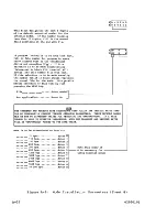
Page 46: ...he internal 1200 1200 baud modem is installed The ON OFF HANGUP ANSWER and DIAL selections are stepped through by pressing the F2 key Selecting HANGUP breaks the current telephone connection Selecting ANSWER places the terminal in auto answer mode Selecting DIAL starts a telephone call sequence without the normal loading process occurring when the telephone connection is made For more details on a...

Page 47: ...T selected Lock key functions as a normal shift lock With ALPHA selected Lock key limits only alpha betical characters to uppercase Governs operation of the 13 keys of the numeric pad group which are on the right side of the keyboard With NORMAL selected these keys operate in lowercase or uppercase as applicable With SHIFT selected the keys only do uppercase functions as if a Shift IJ key is in us...

Page 48: ... the internal 1200 1200 baud modem for communications Governs routing of keyboard data within terminal With HALF selection keyboard data is displayed simultaneously as it is transmitted With FULL selection key board data must be echoed back by host Ibefore being displayed I IDetermines whether 80 or 132 maximum Icharacters are displayed per line When loptional graphics feature is used C must be se...

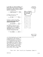
Page 49: ...CTUALLY SHOWN SELECTIONS SHOWN WITHIN PARENTHESIS ARE IN EFFEC l F I FIDUPLEX 5 6 HALF 75 19 2 FULL F CHR LN F LiNEs F XPARENT 7 80 8 24 9 OFF 1 32 3 0 ON INDICATES F10 KEY BRINGS MODE MENU TO SCREEN Figure 4 2 Second Set of Operator Parameters for CYBER Mode PROTECTED SCREEN POSITIONS The host may designate any character position on the screen as protected The contents of protected positions can ...

Page 50: ...ackspaced into a protected position using the keyboard The cursor automatically skips past the protected position and goes to the next or preceding unprotected position as applicable The cursor can be moved up or down into a protected position using the keyboard However any attempt to enter a character in a protected position results in the character being tabbed into the next unprotected position...

Page 51: ... and editing are done pressing one of the keys shown in figure 4 3 will start the block transmission During the transmission the keyboard locks LOCK indicator lights and the cursor moves through the displayed data as it is transmitted If the host instructed the terminal to send to the current position the transmission includes the unprotected data from the top left of the screen up to but not incl...

Page 52: ...n CYBER mode the host may assign special functions or codes to the keys identified in figure 4 4 These keys function as described here unless changed by the host HEAVY LINES SHOW POSSIBLE LOCATIONS OF DOUBLE SIZE KEYCAPS LEGEND II KEYS THAT HAVE NO FUNCTION UNLESS ASSIGNED BY HOST D KEYS WHOSE FUNCTION OR CODES MAY BE CHANGED BY HOST fiJI KEYS THAT HAVE NO FUNCTION UNLESS ASSIGNED BY HOST BUT DO P...

Page 53: ... When two symbols share a key the upper symbol or control function is active while either Shift key is actuated Lock Key The Lock key can be conditioned through operator parameters to function as a normal shift lock or to limit only alphabetical characters to uppercase First pressing of the Lock key initiates the conditioned function and lights the indicator in the key Second pressing of the key h...

Page 54: ...ymbols that display in place of the punctuation and numeric characters listed in table 4 2 Special symbols that display in place of the lowercase uppercase alphabetical characters This correlation is listed in table 4 3 Host loaded symbols that display in place of alphabetical characters in a manner similar to the special symbols but which are undefined This is because each host loaded symbol cons...

Page 55: ...NG LINE DRAWING ALL KEYCAP SETS SYMBOL UNLESS OTHERWISE NOTED 0 A B A B 1 Space 0 dJ I 1 r I JL 2 United Kingdom or l I Spanish or French 3 keycaps I J 4 Other keycap sets JL 1 5 r III L 6 P Swedish Finnish keycaps 7 III 8 T 9 I Apostrophe L Colon l Semicolon L 1 Plus Space Comma II I Minus rF Decimal Point I l 05129 62950101 4 11 ...

Page 56: ...Space keycaps W J Other key cap sets X w A y B Z 0 I C f J French keycaps D F A Swedish Finnish or Ger nan keycaps E 8 i Spanish keycaps F Danish Norwegian G keycaps H Other eyc p sets I I S French keycaps J 0 Swed ish Finnish or German keycaps _ K L N Spanish keycaps Space L II C2 Danish Norwegian M U keycaps N Other keycap sets J 0 French keycaps p a Swedish Finnish or Danish Norwegian Q 3 keyca...

Page 57: ...RWISE NOTED ro A B A B U Swedish Finnish 0 Space keycaps Space p Other keycap sets q Underline l r e Swedish Finnish keycaps s C Grave accent on t other keycap sets u a v I b 0 w I c 0 x d X Y e z f e French keycaps 9 a Swedish Finnish or h v German keycaps _ _ _ _ c _ i t em Dani sh Norwegian keycaps j I 9 Spanish keycaps k Other keycap sets 1 05130 1 m spacel n 62950101 4 13 ...

Page 58: ... Other keycap sets I I V Other sets keycap e French keycaps 1 1 DEL Delete All 0 Swedish Finnish or a Danish Norwegian keycaps l Spanish keycaps _ u German keycaps Other keycap sets I0000 _ __ _ ___ L _ 05130 2 MOVING CURSOR The functions listed in table 4 4 allow the cursor to be moved without affecting displayed data TABLE 4 4 MOVING CURSOR r CURSOR MOVEMENT I PRESS KEY S I I Left one character ...

Page 59: ...ne If the first position is protected and auto matic tabbing is in effect cursor skips past the protected position to the next unprotected position In large CYBER operations with automatic line feed or small CYBER operations move cursor to first position of next line If that position is protected and automatic tabbing is in effect cursor skips past the protected position to the next unprotected po...

Page 60: ...bbing Protection Mode Automatic line feed is a mode installation parameter _ TABBING The tabbing functions available through the keyboard are listed in table 4 5 These functions are similar to the tab set function on a typewriter TABLE 4 5 TABBING FUNCTIONS TAB FUNCTION r I PRESS KEY S I r Set column that cursor is in as a tab stop I CTRLTI Clear column that cursor is in as a tab stop 1 rr 1 II I ...

Page 61: ...for tab forward With full duplex routing tab functions do not occur until codes for keys are echoed back by host These functions cannot be performed if cursor is in a pro tected position EDITING Table 4 6 lists the editing functions available in CYBER mode TABLE 4 6 EDITING FUNCTIONS I EDITING FUNCTION I PRESS KEY S I I I r IClear data from present cursor position for I Iward to end of line or unt...

Page 62: ...tion and the unprotected position is cleared Automatic tabbing is described earlier in this section under Automatic Tabbing Protection Mode If cursor is in a protected position use of the ERASE key results in the alarm sounding No other action is taken Delete character at present cursor position and sbift characters right of cursor one position left If protected positions are right of cursor shift...

Page 63: ...ions do not occ r until codes for keys are echoed or sent back by host CONTROLLING COMMUNICATIONS AND PRINTING The keyboard functions that control communications and printing in CYBER mode are listed in table 4 7 TABLE 4 7 CONTROLLING COMMUNICATIONS AND PRINTING I FUNCTION I PRESS KEY S I T Do a manual release This B aborts all host communications and print transfers and if key board is locked unl...

Page 64: ...LOCK indicator lights and received data is temporarily ignored Same type print transfer just described except dimmed data is replaced with space codes Transmit a break signal ITransmit a delete code I ITransmit an escape code I t HOST CONTROLLED FUNCTIONS In CYBER mode the host can direct the terminal to Load a program from host Load up to 64 separate symbol patterns from host Perform special func...

Page 65: ...y coded alphanumeric characters Enable disable touchpanel use Enable disable transmission to host Perform a self test similar to power on test and notify host whether a failure occurred or not Light ALERT indicator MESSAGE indicator or PROGRAM indicators Transfer data to printer or stop transfer to printer Switch from CYBER mode to a new designated operating mode mode 3 through 7 62950101 4 21 ...

Page 66: ......

Page 67: ... can cause defective key operation and damage keycaps 2 Dust keyboard with soft bristled brush CLEANING CABINET AND SCREEN 1 Turn off terminal by pressing side of POWER switch marked with the O 2 Wipe exterior of terminal cabinet using a soft damp lint free cloth 3 Clean screen or touchpanel using a soft lint free cloth dampened with a mild soap and water solution Do not allow cleaning solution to...

Page 68: ......

Page 69: ...ist various symptoms with recommended corrective actions Some actions may require assistance from supervisory personnel The type problems covered are listed below with their corresponding table number The tables assume that the terminal has been installed and checked out per appendix A and that the terminal battery has kept installation parameters stored in nonvolatile memory loss of installation ...

Page 70: ... rear of terminal and retry POWER switch 4 Check outlet for power by connecting a different device to outlet If that device does not operate either notify building electrician If device operates OK basic terminal unit and power cord need maintenance attention 1 If 50 Hz power is being used verify that LINE VOLTAGE switch qt rear of terminal is set for 220 240 V 2 Basic terminal unit needs maintena...

Page 71: ...CLOCK FAIL EXT KBD LOOPBACK FAIL 62950101 ICheck that terminal has lpower for power problems Irefer to table 6 1 If it Ihas power do the correc Itive actions listed in Itable 6 6 for meaningless lor no data displays 1 symptom 1 I 1 1 1 1 Basic terminal unit I needs maintenance 1 attention 1 1 1 1 1 1 1 1 1 IHave your supervisor re lenter and copy all instal Ilation parameters into non Ivolatile me...

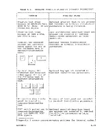
Page 72: ...t I I needs maintenance I I attention 1 ITEST NORMAL switch on dual lasynchronous interface Iboard in I F 1 through II F 3 is in the TEST posi Ition Set switch to the INORMAL position for normal Ioperation _ _ _ I______ __ __ ______ If items requlrlng maintenance attention are to be turned in to a CDC repair service center refer to the latter portion of this section for instructions TABLE 6 3 HOST...

Page 73: ...work equi ment and local phone equipment are operational manual dial and listen 5 Basic terminal unit needs maintenance attention 1 If screen shows block 0 loading and then NO REPLY appears verify that a valid file number is being entered 2 Verify that host computer and commu nications network are operational 3 Enter operator intervention test and check transmit and receive circuits using rrEST NO...

Page 74: ...ng maintenance attention are to be turned in to a CDC repair service center refer to the latter portion of this section for instructions TABLE 6 4 SYMPI OM Attempting to load from a memory module and FAILURE LOADING MODE shows on screen and alann sounds MEMORY MODULE LOADING PROBLEMS ACTIONS TO BE DONE UNTIL PROBLEM IS CORRECTED OR RESOLVED 1 Verify that memory module is installed in terminal Sect...

Page 75: ...with notches in bezel 1 1 IHave your supervisor realign crt Iper appendix A I IWrong code appears for a IPu11 out TEST switch at rear of key or code does not changeltermina1 If KBD FAIL or KBD CLOCK when key is released IFAIL is displayed basic terminal lunit needs maintenance attention 1otherwise keyboard needs mainte Inance attention One or more indicators on front of terminal do not light durin...

Page 76: ...asic terminal unit plus any boards in I F l through I F 3 slots need maintenance attention Do the following actions until problem is corrected or resolved Recheck test results after each action by momentarily pushing TEST switch in and then pulling it back out This reruns test and if problem is corrected PARALLEL PORT OK displays If a Flexible Disk Drive is on the parallel channel it must be power...

Page 77: ...Ubstitute printer and cable if available in place of original printer and cable c If substitute printer does not have a terminator in stall terminator fram original unit d Press in TEST switch on terminal then power on printer and terminal e Press PRINT indicator switch on printer to light indicator f Refer to section 3 and reenter operator intervention test g Pullout TEST switch If PARALLEL PORT ...

Page 78: ...M CORRECTIVE ACTION I T ICheck that terminal has power I for power problems re fer to table 6 1 If terminal has power verify that BRIGHTNESS or CONTRAST control did not accidentally get turned too far counterclockwise If that is not the problem basic terminal unit or board in rear slot I F 1 through I F 3 needs maintenance attention If terminal is covered by a carry in mainte nance agreement deter...

Page 79: ...erat ing properly This is because the board is removed d If display still does not operate correctly the basic terminal unit needs mainte nance attention otherwise the board s removed in step b needs maintenance attention Have your supervisor verify that correct language is selected in terminal installation parameters If that is not the problem basic terminal unit needs maintenance attention Press...

Page 80: ...te if a dual asynchronous interface board was removed a PORT A FAIL and PORT B FAIL message will appear if display is operat ing properly This is be cause the board is removed t d If display still does not 1 operate correctly the basic I terminal unit needs mainte 1 nance attention otherwise 1 the board s removed in 1 step b needs maintenance I attention 1 Display not stable 1 1 I I Basic terminal...

Page 81: ...y goes light to dark If no change occurs basic terminal unit needs maintenance attention Check that BRIGHTNESS control is not too far clockwise If that is not the problem basic terminal unit needs maintenance attention I Enter operator intervention 1 test section 3 contains 1 instructions Check whether 1 alignment border in test is I in line with notches in bezel 1 If border is not in line have yo...

Page 82: ... RESET switch to rerun power on test 3 If KBD CLOCK FAIL or EXT KBD LOOPBACK FAIL appears on screen basic terminal unit needs maintenance attention other wise keyboard needs maintenance attention Enter operator intervention test and check whether correct code appears when key is pressed sec tion 3 contains instructions If correct code appears problem is likely not with keyboard or termi nal but wi...

Page 83: ...ine with host check that connected modem is operational and that DATA SET READY indicator is lit on terminal If that is not the problem unlock keyboard by pressing RESEfr switch If condition reoccurs call hotline number for assistance Enter operator intervention test and check whether touchpanel operates correctly in test sec tion 3 contains instructions If it does touchpanel input was probably no...

Page 84: ...o a test print or self test success fully refer to printer operator s guide for applicable procedure If it cannot printer needs maintenance attention 3 If printer has been reconnected and is a serial interface character or graphics printer verify it is connected to the correct connector at terminal Connector Jl is for port A operations and connector J2 is for port B operations Which port is correc...

Page 85: ...eck that printer and termi nal port are using same data rate parity and number of stop bits These characteristics on terminal port are determined by installation parameters Correlation between port and terminal connector is that connector Jl is for port A opera tions and connector J2 is for port B operations 2 If this problem is occurring with a parallel interface graphics printer check that FTl16...

Page 86: ...l inform you of the nearest available repair service center Always check with the representative before shipping an item because the location of repair service centers occasionally change and a newly opened center may be closer All items turned in either by person or by shipment must be packed in CDC approved materials If original packing materials were not saved approved materials may be obtained...

Page 87: ...rent parameters 2 Turn off power to terminal and to all devices connected to terminal 3 Disconnect the following Terminal power cord at both ends Keyboard cable from terminal All device interconnecting cables from terminal it maybe desirable to tag these cables to facilitate reconnect ion later 4 If any printed circuit boards are in the I F I through I F 3 slots at rear of terminal figure 6 1 they...

Page 88: ... pack basic terminal unit using original packing materials or approved replaced materials 8 Place bag with coiled power cord on top of terminal unit and tape to inside of carton 9 Seal basic terminal carton with 3 inch box sealing tape 10 Proceed to instructions on Accompanying Information 62950101 ...

Page 89: ... TAPE TO INSIDE OF CARTON FRONT OF TERMINAL GOES IN END OF CARTON HAVING CDC LOGO LARGER FOAM CAP AT REAR FOAM END CAPS 2 SETS PART NO 90538401 DISPLAY TERMINAL CARTON PART NO 90538403 04221 1 Figure 6 2 Packing Basic Terminal unit 62950101 6 21 ...

Page 90: ... sealing tape 4 Proceed to instructions on Accompanying Information CARTON END KEYBOARD CARTON PART NUMBER 90538404 HAVING CDC LOGO 04221 4 Figure 6 3 Packing Keyboard PREPARING OPTIONAL BOARD IN I F 1 THROUGH I F 3 FOR TURN IN To prepare an optional board in one of the rear slots I F I through I F 3 for turn in do as follows 1 Turn off power to terminal and to all devices that are connected to ba...

Page 91: ...d container with cushioning material 5 Proceed to instructions on Accompanying Information ACCOMPANYING INFORMATION The following information must accompany the turned in item The company name and address of the user The name and telephone number of the person to be contacted if any questions arise The failure that occurred The contract number or account number of the maintenance agreement The eig...

Page 92: ......

Page 93: ... m 3 ft to permit servicing Avoid direct sunlight on display screen Allow a 102 mm 4 in minimum space at top and sides of terminal for adequate cooling Avoid installing the terminal in areas of high electromagnetic interference Such areas usually exist near radio transmitting antennas radar induction heaters arc welders insulation testers time clocks certain electrical heating systems and high ene...

Page 94: ... terminal The recommended cable is CDC 799 10 equipment number YA255 A which is 3 meters 10 feet long and meets RS 232 C requirements See Appendix B if using internal modem TERMINAL PREPARATION These instructions assume that the terminal the keyboard and optional items have been unpacked per the instruction sheet that was included with shipping papers With that done do as follows 1 Place terminal ...

Page 95: ... XA368 A graphics board is to be installed install per the instructions that carne with the item 6 If a YRI0I A dual asynchronous interface board or YRI02 A parallel interface board is to be installed proceed to instructions for Board Installation in I F 1 through I F 3 otherwise proceed to instructions for Cable Installation LINE VOLTAGE SWITCH SHOWN SET FOR 120 V CONNECTION FOR KEYBOARD CABLE 04...

Page 96: ...e cover plate for remounting if basic terminal is shipped to a service center CAUTION Be sure board is aligned with slot connector before pushing on board during next step 3 Insert optional board in I F l slot as shown in figure A 2 4 Use the two screws removed in step 1 and secure cover plate of board to rear of terminal S If a TEST NORMAL switch is on cover plate of board check that switch is in...

Page 97: ...e cable connections for the equipment arrangements listed below refer to Appendix B for installing a terminal using an internal modem Refer to the appropriate figure s and be sure to tighten screws when connecting cables with connector retainers Equipment Arrangement Host communications via external modem Host communications via direct cable Associated asynchronous communication peripheral Associa...

Page 98: ... YA255 A CABLE OR EQUIVALENT STANDARD ACOUSTIC COUPLER TERMINAL DATASET CONNECTOR 03910 8 STANDARD ACOUSTIC COUPLER MULTI BUTTON TELEPHONE WITH EXCLUSION FUNCTION YA255 A CABLE OR EQUIVALENT WESTERN ELECTRIC 212A DATAPHONE D CABLE PROVIDED WITH TELEPHONE TELEPHONE WALL BOX TERMINAL DATA SET CONNECTOR 03910 8 DATAPHONE Figure A 3 Host Communications Via External Modem A 6 62950101 ...

Page 99: ...ERAL r INTERFACE IN 1 J t I F I I F 2 OR I 3 SLOT FOR OPERATION ON PORT At CONNECT CABLE TO JI FOR OPERATION ON DUAL ASYNCHRONOUS INTERFACE BOARD PORT Bt CONNECT CABLE TO J2 03910 12 Figure A 5 Associated Asynchronous Communication Peripheral CABLE PROVIDED WITH PRINTER PARALLEL INTERFACE GRAPHICS PRINTER TERMINAL 1 PARALLEL I 1 INTERFACE I IN I F I I F 2 I lOR I F 3 SLOT I PARALLEL CON ECTOR Figu...

Page 100: ...ch is in the way of the receptacle push the latch down PUSH DOWN TO ACCESS RECEPTACLE NOT ON EARLIER MODELS iiT iT ri 4 W RECEPTACLE Figure A 7 Accessing Power Cord Receptacle CAUTION The next step assumes that the terminal is conditioned for existing power voltage The terminal comes from the factory conditioned for 120 V ac 60 Hz operation For 50 Hz operation at 220 240 V ac the YA275 A power con...

Page 101: ...ctory set for a typically configured terminal and for the most commonly used operating modes Changes may be required for installed options or for certain applications such changes will be noted in the option or application documentation The instructions here cover all parameters in detail so that future changes may be made easily Refer to appendix B for parameters specifically related to the inter...

Page 102: ...al with the configuration of the terminal NOTE The next step assumes that the mode menu is on the screen after Initial Power On instructions have been done If existing parameters are being accessed mode menu is displayed by doing as follows If operating in CYBER mode press SETUP key then FlO key twice If not in CYBER mode and terminal is conditioned for manual selection of operating mode press RES...

Page 103: ...eferred to where applicable in the procedure Pressing a disabled key sounds the alarm 3 Square cursor in F2 block of menu indicates where first entry is Each succeeding block through F9 contains further entries Refer to figure A 8 and follow instructions on figure 62950101 A II ...

Page 104: ...HANGE IS REQUIRED PRESS THE F2 THROUGH F9 KEY THAT CORRE SPONDS WITH THE NUMBERED BLOCK WHERE CHANGE IS TO BE MADE THIS MOVES CURSOR WITHIN THAT BroCK USE SPACE BAR TO GO FORWARD OR BACKSPACE KEY Eo TO GO BACKWARD AND MOVE CURSOR TO DIGIT OF WRONG VALUE THEN KEY IN NEW DIGIT Touchpanel installed Dual asynchronous interface board installed Parallel interface graphic printer installed Flexible disk ...

Page 105: ...is in a mark ing state The CK130 printers CK208 CK209 and CK210 printers do not require this delay If 1200 1200 bls internal modem is installed are its self tests to run whenever the terminal power on test runs Modem _I Yes No Enter Enter Not used Enter Enter _I Yes No Enter J Enter _I Yes No Not used Enter 1 _I s Enter 0_1 I Enabled Enter 0 1 _1 _Disabled__ Enter FIC 0 NFl GI 4 0 0 0 0 0 01 _I us...

Page 106: ...ional peripheral must be powered on and ready during online operations If this is not done communications with host may be tied up waiting for the printer bidirectional peripheral to become ready Figure A B Terminal Installation Parameters Sheet 3 A 14 62950101 ...

Page 107: ...al code in the space below CYBER mode Enter 0 or PLATO mode Enter 2 Mode 3 Enter 3 Mode 4 Enter 4 Mode 5 Enter 5 Mode 6 Enter 6 Mode in memory module ROM pack Enter 7 Standard Enter 0 or French Enter 2 German Enter 3 Swedish Finnish Enter 4 united Kingdom Enter 5 Spanish Enter 6 Danish Norwegian Enter 7 F A S X y 6 0 0 0 1J I F L I D 7 0 0 0 0 0 1 Terminal ID code Enter code if any Modes 3 4 and 5...

Page 108: ...serted bit to be a mark or a space __Mark 11 __Space or not applicable Excluding parity or inserted mark or space words in Port A communi cations are to have __Eight data bitS 1 O Seven data bits 2 digit 000 0 000 1 0 0 0 001 1 o 1 0 0 0 0 1 o 0 o 1 1 000 001 1 0 0 1 0 1 1 100 o 1 1 0 1 o 2 3 4 5 6 7 8 9 A B C D E F I 75 bps Enter 0 110 bps Enter 1 150 bps Enter 2 200 bps Enter 3 300 bps Enter 4 D...

Page 109: ...ed bit to be a mark or a space __Mark 1 __space or not applicable Q Excluding parity or inserted mark or space words in port B communi cations are to have __Eight data bitS O Seven data bits O 2 Data rate on port B is to be 1 1 75 110 150 200 300 600 digit 23 22 21 20 Hex o 0 o 0 o 0 o 0 o 1 o 1 o o 1 o o o o 1 o 0 o 1 o 1 o 0 o 1 o 1 o 0 o 1 1 0 1 o 0 o o 1 o 2 3 4 5 6 7 8 9 A B C D E F bps Enter...

Page 110: ... operate in If operations are to occur in more than one mode enter number of lowest number mode If number entered is 3 4 5 or 6 ENTER MODE NAME appears on screen if number entered is 1 or 2 menu of mode installation parameters appears figure A 9 With modes 3 through 5 the name of the preassigned mode appears adjacent to ENTER MODE NAME 8 If ENTER MODE NAME is displayed and a mode name already exis...

Page 111: ...be entered before operations can take place If so only persons who know the designated access code can operate mode Are phone number source and file for program loading to be selected by operator or auto matically selected default values selected from parameter entries Enabled Disabled _I yes No Manually Automatically Not applicable for CYBER Mode Are operations to be in CYBER mode _ I Load extern...

Page 112: ... Enter 0 r If parity in host communications Even Enter is enabled parity is to be _Odd Enter 0 If parity in host communications is disabled and words have seven I Mark Enter data bits an eighth bit will be Space or not inserted in the parity bit _applicable Enter 0 position Is the inserted bit to be a mark or a space 1 Are words in host communications Two Enter to have one or two stop bits One Ent...

Page 113: ...sed a switched RTS goes on with the first keyboard entry and drops Upon receipt of a break a received word containing a space in the stop bit position During local operations Not applicable Enter 0 Following the transmission of Switched RTS Enter 1 a CR OD16 LF OA16 ACK 0616 or NAK 1516 code Constant RTS Enter 0 Not applicable Enter 0 Are data entry and control keys to be typamatic start repeating...

Page 114: ...ving X Y positioning data to from host 2016 added when sending to host and 2016 subtracted when receiving I Yes __Enter 1 No Enter 0 The cursor automatically advances I stay __Enter to the beginning of the next line when keyboard entries fill a line Advance Enter 0 Is this also to be done when data from host fills a line or is cursor to stay at the end of a line until advanced by host NF I Gol 000...

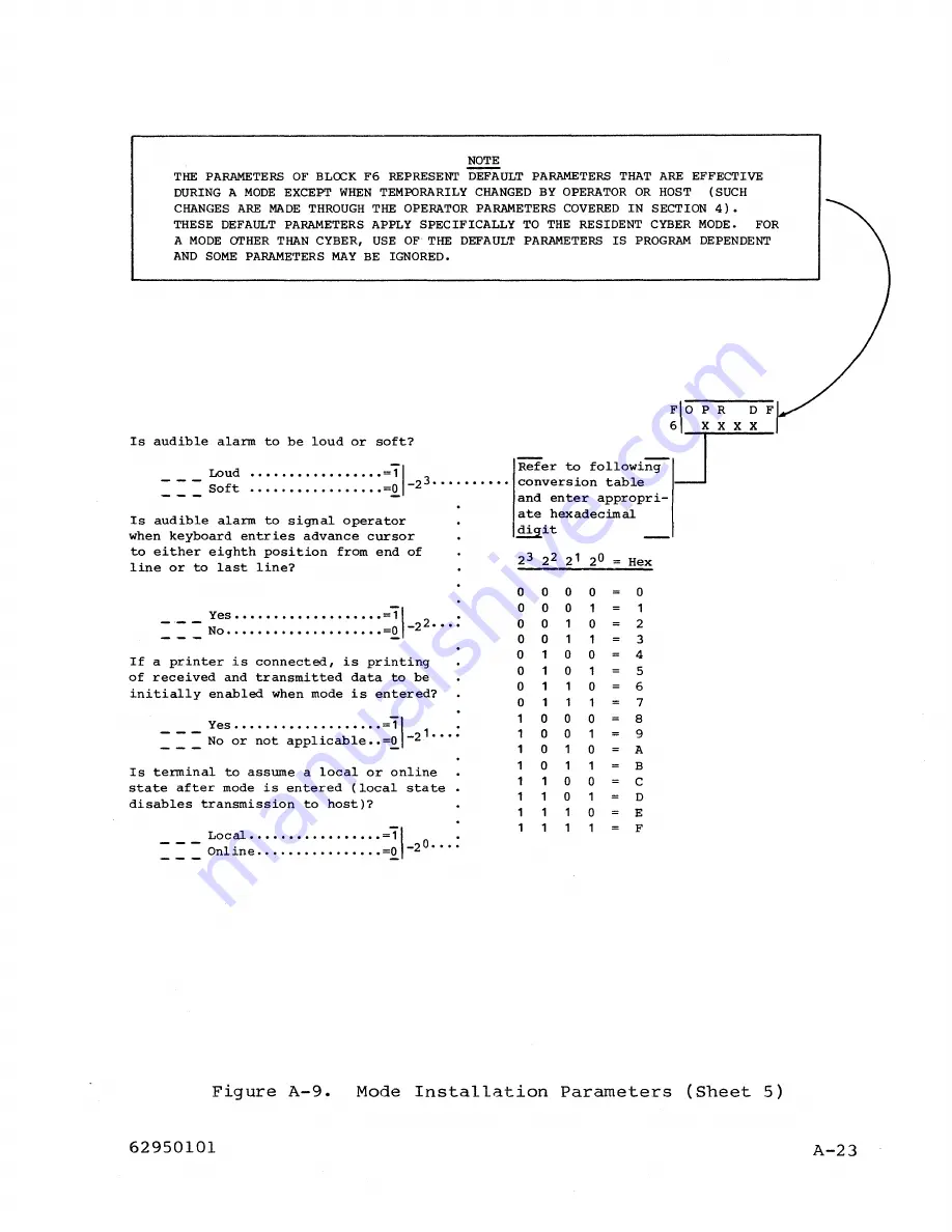
Page 115: ...l operator when keyboard entries advance cursor to either eighth position from end of line or to last line Yes 1 No 0 22 If a printer is connected is printing of received and transmitted data to be initially enabled when mode is entered _ _ _ yes 1 1 ___ No or not applicable 2 Is terminal to assume a local or online state after mode is entered local state disables transmission to host Local 1 Onli...

Page 116: ...illuminated or blink Steady 1 22 ___ BIl nk Is cursor to be in the form of an underline or a block Block 1 1 2 Underline O Is display screen to show light characters on dark background or dark characters on light background inverse video Light background 1 0 2 ___ Dark background Refer to followi g conversion table l and enter appropri ate hexadecimal digit __ I 2 3 22 21 20 Hex 0 0 0 0 0 0 0 0 0 ...

Page 117: ...ltaneously as it is transmitted half duplex routing or is it to be echoed back by host before being displayed full duplex routing Full duplex 1 d 1 20 Half up ex o 000 000 0 0 0 0 0 1 0 0 0 0 0 1 o 1 0 o 1 000 001 010 o 1 100 1 0 o Hex o 2 3 4 5 6 7 8 9 A B C D E F F A D I A LI 7 0 0 0 0 0 01 I I This field designates the first 6 digits of the default auto dial number that the internal modem is to...

Page 118: ...ng the NEXT key FIDF 9 OX L File____________ Enter numberl______________________________ Not applicable Enter 00 NOTE T X I THE TRANSMIT AND RECEIVE RATE SELECTIONS THAT FOLLOW ARE DEFAULT RATES THAT CAN BE TEMPORARILY CHANGED THROUGH OPERATOR PARAMETERS THESE DEFAULT RATES MAY BE SET TO DIFFERENT VALUES FOR RECEIVING AND TRANSMITTING IF A RATE CHANGE IS MADE IN OPERATOR PARAMETERS BOTH THE TRANSM...

Page 119: ...sing internal modem F DF 9 OX T X I If access code parameter in block F2 I was not selected disregard the following and do not make any entries _ Fill in access code for mode in space below or if desired record elsewhere for future reference This assigned code is to consist of four digits that may be any hexadecimal value Once parameters are established operations in a mode will only be allowed af...

Page 120: ...n section 6 1 Attach the yellow and black Repair Service tag you received in the keyboard carton where it is handy for reference The numbers on this tag are Control Data hotline numbers which you may call if you have equipment problems that you cannot solve In the blank box on the tag enter the phone number of the repair center in your area You can find the number in the pamphlet that came with th...

Page 121: ...ct codes appear for one of the following keys in operator intervention test INo reaction when touch Ipanel is touched in operator intervention Itest I TEST switch pulled out operator intervention test and PARALLEL PORT IFAIL appears Dual asynchronous interface board not presen t but recorded in terminal installation parameters as being installed Optional keycaps inadvertently recorded in terminal ...

Page 122: ...ing Receive transmit rate for host can munications entered in mode installa tion parameters is incorrect Invalid file number recorded in mode installation parameters Any of the following Number of auto select mode entered in terminal installation parameters does not match the number of the mode for which mode installation parameters have been established invalid mode being selected Specified auto ...

Page 123: ...tion parameters is incorrect Host does not echo data back and full duplex internal routing is designated in mode installation parame ters Host does echo data back and ha1f duplex internal routing is designated lin mode installation parameters Selection regarding biasing of cursor address is incorrect in mode instal lation parameters If in CYBER mode coding selected in mode installation parameters ...

Page 124: ...ect this condition the basic terminal unit needs maintenance attention To realign the crt do as follows 1 If the display for the operator intervention test is currently on the screen figure A IO disregard this step and step 2 otherwise make the mode menu appear by doing the applicable actions that follow If operating in CYBER mode press SETUP key then FlO key twice If not in CYBER mode and termina...

Page 125: ...A IO Use those as a guide and estimate the distance to be corrected as follows If border is off center horizontally estimate how many character positions right or left that the border must move If border is off center vertically estimate how many scan lines up or down that the border must move To see the scan lines on the screen momentarily turn the BRIGHTNESS control nearly all the way clockwise ...

Page 126: ... NONE 9 DOWN 1 A DOWN 2 B DOWN 3 C DOWN 4 D DOWN 5 E DOWN 6 F DOWN 7 Figure A II Realignment Entries 6 Press F6 key to advance cursor into block F6 Then use Space bar to advance cursor under X if horizontal realignment is required or under Y if vertical realignment is required If cursor is advanced too far backspace cursor with Backspace key A 34 7 Refer to figure A II and make applicable keyboard...

Page 127: ... If not in CYBER mode and terminal is conditioned for manual selection of operating mode press RESET switch menu appears after power on test If not in CYBER mode and terminal is conditioned for automatic selection of operating mode pullout TEST switch at rear of terminal then press RESET switch This shows a DIAGNOSTIC FAILURE message along with the mode selection menu Disregard the failure message...

Page 128: ...uired correction value for later entry in terminal installation parameters 8 For vertical alignment verify the relative position of your 1 and 30 entries on the display screen match those indicated in figure A 12 1 in lower part of upper left grid and 30 in upper part of lower left grid If positioning is not correct refer to figure A II to determine correction necessary for Y entry of F6 of termin...

Page 129: ...6 X 16 TOUCH PANEL GRID VISIBLE WHEN IN INVERSE VIDEO HORIZONTAL REFERENCE 1 123456789 30 1 1 1 i 1 r 05131 VERTICAL REFERENCE Figure A 12 Display Alignment Pattern for Use with Touchpanel 62950101 A 37 ...

Page 130: ......

Page 131: ...ber of the modern is XA360 A and it is installed in large option board location I F 4 refer to figure B 1 The presence of this modem in the terminal is most easily established by checking the I F 4 location at the rear of the terminal The rear of the modem with its Canadian Department of Communications and FCC certification label is prcminently visible through a slot in the rear of the terminal at...

Page 132: ...ing Autanat ic dual tone multi frequency dialing touch tone Automatic pulse dialing standard dial phone dialing Operation in auto answer mode Operation in either call originate or call answer mode Operation in both digital and analog loopback test mode A firmware resident self test feature Standard telephone line interface 1 a RJIIC modular phone jack connector accessible at rear of terminal and 2...

Page 133: ...lation parameters This entry position should be a 1 if you desire that the loopback test be run with the other modem self tests the loopback test takes approximately 10 seconds to complete or be a o if you do not desire it to run with the other self tests Following is a listing of the fault messages associated with the modem self tests If anyone of these messages appear on the terminal screen foll...

Page 134: ...ult of this action the follow ing message appears on the terminal display screen ENTER PHONE NUMBER 2 Keys in the desired phone number on the terminal keyboard The following characters are permissible for making phone number entries on the terminal keyboard the terminal does not accept key entries other than those listed below o to 9 these digits are used to make standard telephone number entries ...

Page 135: ...hat auto matically enters a phone number and selects the load source and file is very similar except that the boxed in display messages do not appear operator only monitors call status and is not required to make entries The following text describes the steps depicted in figure B 2 in more detail ENTER PHONE NUMBER this is the initial message that appears on the display screen during an auto dial ...

Page 136: ... block of the selected file loads Possible Display Messa es NO DIAL TONE ENTER PHONE NUMBER DIALING PHONE NUMBER ILLEGAL DIGIT WAITING FOR ANSWER I I I DIALING BUSY RINGING ERROR NO ANSWER SELECT LOAD SOURCE DISK HOST ROM LOADING FILE XX I LOADING FILE xx BLOCK YY 05127 The last message HOST HOT CONNECTED only appears if the source select message is entered via the no dial tone illegal digit diali...

Page 137: ... therefore follow the no connection path to the SELECT LOAD SOURCE etc message The last of the three possible messages ringing indicates that the number dialed has been reached and that the dialed device is ringing This message can still lead to one last possible no connection message or it can take a connection completed path NO ANSWER this is the last of the no connection messages It indicates t...

Page 138: ...nternal modern These messages occur only if the terminal has not made a proper telephone line connection with the host computer In such an instance a HOST NOT CONNECTED message appears a short time after the terminal operator presses the H and NEXT keys of the terminal to initiate the download operation If the terminal has not established a communications line connection within 40 seconds after th...

Page 139: ...on the screen for approx imately 40 seconds before it is replaced by other messages that indicate a loading failure has occurred The 40 second interval allows the terminal operator time to complete the following step 3 Dial the desired telephone number on a hand set wait for the phone to be answered and to hear the answer tone and hang up the telephone hand piece 4 At this point the internal modem...

Page 140: ... parameters that are associated with the internal modem For information on how to install the modem into the terminal user installation of the modem only applies to CC634 B or CC638 B terminals refer to the Hardware Installation Instructions that came with the modem preface lists the publication number CONNECTING MODEM EQUIPPED TRRMINAL TO TELEPHONE LINE To connect a terminal to the telephone line...

Page 141: ...tment of Communica tions guidelines require that a tool is necessary to disconnect communi cations cords or cables from their associated communications devices To conform to Canadian requirements the terminal device ends of all extension cords furnished with internal modem equipped terminals have had the retaining clips of their RJll plugs shortened slightly so that a tool is necessary to remove t...

Page 142: ... wall jack refer to figure B 4d 5 Check that completed installation appears as shown in figure B 5 NOTE The installation must appear as shown in the figure B 5 The installation will not function properly with the duplex jack plug of the furnished extension cord connected to the rear of the terminal or to the body or hand piece of the telephone INSTALLATION PARAMETER MODIFICATION This portion of th...

Page 143: ...WALL JACK a INSERT FREE END OF MODEM PHONE CORD INTO MODEM c AT REAR OF TERMINAL b INSERT DUPLEX ADAPTER INTO WALL JACK 05126 INSERT PHONE CORD PLUG INTO OPEN JACK OF DUPLEX d PLUG Figure B 4 Installing a Modem Equipped Terminal 62950101 B 13 ...

Page 144: ...05125 Figure B S Completed Installation of Modem Equipped Terminal B 14 62950101 ...

Page 145: ... action to occur If this latter action occurs forcing an error condition causes both an error message and the mode selection menu to display An error condition may be forced by 1 Pulling out the TEST switch at rear of tenninal refer to figure B 6 2 Pressing the RESET switch at front of terminal 3 Pushing the TEST switch at rear of terminal back in as soon as the mode menu appears near the bottom o...

Page 146: ...ns 1 of the F3 field and 3 and 4 of the F4 field relate to the internal modem Press the F3 key to move the cursor to position 1 of the F3 field 4 Position 1 of the F3 field must be a 1 if the 1200 1200 b s internal modem is installed or be a 0 if it is not installed Make the necessary entry by pressing the appropriate numbered key 5 Press the F4 key to move the cursor into the F4 field The cursor ...

Page 147: ...n parameters menu to appear below the prompt F I I F CONFiG F CONFiG FICoNFiG F CoNFiGI F IOPRD FI FIA DIiL1 FIA DIiL1 FIDFTRI FIACcESSI 1__ 2 100XXO 3 4 5 6 7 81 1 91 1 101 1 Mode Installation Parameters Menu Parameter entry positions 3 and 6 of the F2 field and positions 1 and 2 of the F3 field are related to the 1200 1200 b s modem The F7 F8 and F9 fields also contain entries relating to the 12...

Page 148: ...ber an alternate telephone number follows in the combined F7 and F8 fields The B and the C alpha characters represent the tone dial symbols and respectively The D and the E alpha characters are both used for inserting pauses in the number dialing sequence The D character inserts a pause in the dialing sequence until a tone is received and the E character inserts a 3 second pause in a dialing seque...

Page 149: ...key the Space bar and the appropriate function keys F2 through FlO to move the cursor to the proper locations for making the required entries 20 Press the COpy key to complete the entry of the mode installation parameters 21 Press the F1 key to return to the mode menu 62950101 B 19 ...

Page 150: ......

Page 151: ...62950101 REVISION A NAME COMPANY ____ _ ___ __ _ _ STREET ADDRESS _ _ CITY STATE ZIP CODE This form is not intended to be used as an order blank Control Data Corporation welcomes your evaluation of this manual Please indicate any errors suggested additions or deletions or general corrunents below please include page number references NO POSTAGE STAMP NECESSARY IF MAILED IN U S A ...

Page 152: ... NO 8241 POSTAGE WILL BE PAID BY CONTROL DATA CORPORATION Technical Publications Department 2401 North Fairview Avenue St Paul Minnesota 55113 MINNEAPOLIS MINN NO POSTAGE NECESSARY IF MAILEO IN THE UNITED 51AYES w z o z o I I u OlD FOLD I I I I I I I I I I I I I I 1M Is ...

Page 153: ......
Page 154: ...CORPORATE HEADQUARTERS P O BOX 0 MINNEAPOLIS MINN 55440 LITHO IN U S A SALES OFFICES AND SERVICE CENTERS IN MAJOR CITIES THROUGHOUT THE WORLD CONT OL DATA COf POR TION ...

Reviews: