26
Unidrive Regen Installation Guide
www.controltechniques.com
Issue Number: 2
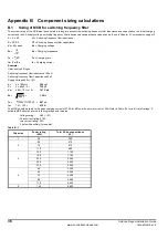
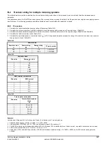
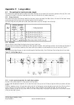
drive is not exceeded. If the power flow from the supply is reduced (i.e. less power is taken from the supply or more power is fed back into the supply)
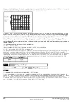
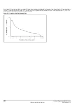
the DC bus voltage will rise. During a rapid transient the bus will rise and then fall as shown below:
The example shown is for a very rapid load change where the torque reference of the motoring drive has been changed instantly from one value to
another. In most applications where the motoring drive is operating under speed control the speed controller may only require a limited rate of change
of torque demand, reducing the rate of change of power flow, and also reducing the size of the transient voltage. If the set point voltage (Pr 15.07)
plus the transient rise exceed the over-voltage trip level (830V for a medium voltage drive) the Regen drive will trip.
When a 400V motor is operated above base speed from a drive in vector mode, fed from the Regen drive supplying a DC voltage of 700V, and an
instantaneous change of torque is demanded (i.e. - 100% to +100%) the peak of the voltage transient (
∆
V) is approximately 80V if the current
controllers are set up correctly. (Operating with maximum voltage on the motor, i.e. above base speed, gives the biggest transient of power and hence
the biggest value of
∆
V).
If
∆
V is required for a different load change it can be calculated from
∆
V = 80V x load change / 200%
If the motor voltage is not 400V or the DC bus voltage set point is not 700V,
∆
V is calculated from
∆
V = 80V x (motor voltage / 400) x (700 / DC bus voltage set point)
In some applications, particularly with a high DC bus voltage set point and low switching frequency it may be necessary to limit the rate of change of
power flow to prevent over voltage trips. A first order filter on the torque reference of the motoring drive (i.e. using Pr 4.12) is the most effective
method to reduce the transient further. (A fixed limit of the rate of change of torque demand is less effective). The following table gives an approximate
indication of the reduction in
∆
V for different time constants. As already mentioned the value of
∆
V given if for an instantaneous change of torque
representing the worst case. In most applications where a speed controller is used in the motoring drive the transient will already include a filter.
N
This parameter is only available when the software version is 3.01.07 or higher.
The voltage controller gain is set to a value that is suitable for most applications. The per drive capacitance of each size of drive is not always the
same, and so the drive compensates so that the gain is set for twice the capacitance of an individual drive as this is the normal situation with a Regen
drive and motoring drive of equal rating. The transient voltage with a sudden change of load,
∆
V, is affected proportionally by this parameter.
Therefore the gain may be changed when the DC bus capacitance is not equal to twice the Regen drive capacitance. However, care must be taken to
ensure that the gain is not too high as this can cause excessive ripple in the DC bus voltage.
Time constant
Change in
∆
V
20ms
x 0.75
40ms
x 0.5
15.21
Voltage control P gain
ô
0 to 30000
ð
4000
RW
Uni
NOTE


