background image

28

Unidrive Regen Installation Guide

www.controltechniques.com

Issue Number: 2

9

Commissioning and operation

9.1

Regen parameter settings

9.1.1

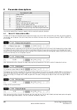
Switching frequency Pr 15.08 (Pr 0.18)

Set the switching frequency on the Regen drive to the required value (3kHz default value).

A higher switching frequency setting has the following advantages:

Line current ripple at the switching frequency is reduced, giving improved waveform quality.

Acoustic noise produced by the line inductors is reduced.

Dynamic DC bus voltage response is improved.

N

In some cases, setting the switching frequency to a value greater than the default 3kHz results in current derating. Refer to the Unidrive size 1 to 4 / 5
Installation Guide.

9.1.2

DC bus voltage set point

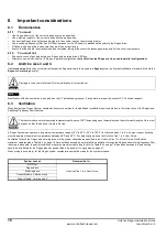
The DC bus voltage set point, see Pr 15.07 (Pr 0.17), should be set to a level that is suitable for the AC supply voltage being used. The table below
defines these levels, assuming a tolerance of

±

10% on the supply voltage (default value is 700V). The minimum value is defined as the peak input

voltage plus some headroom. Headroom is required by the drive to allow correct control of the current. It is advisable to set the voltage below the
maximum value to give more allowance for transient voltage overshoots. Note that Pr 15.07 (Pr 0.17) can be set to any value between 0 and 800V.

Table 9-1

DC bus voltage set point - Pr 15.07 (Pr 0.17)

9.2

Regen drive sequencing

When a Regen drive is enabled, it goes through a line synchronisation sequence. During this procedure, test pulses are applied to the incoming line
to determine the voltage and phase. When it has been successfully synchronised to the line, the DC bus voltage controller is enabled and the DC bus
voltage rises to the target voltage.

Only when all of these stages have been completed successfully is the motoring drive enabled. If at any time there is a fault, or the Regen drive is
disabled, the motoring drive will also be disabled.

This sequence of events is important to prevent damage to the Regen drive, motoring drive or external power circuit components.

The sequence of events is as follows:

Power applied:

both contactors de-energised

DC bus charges through start-up resistor

DC bus voltage equals

2 Vac

if DC bus voltage > UU trip level then auxiliary contactor is energised. This closes the main contactor and shorts out the start-up circuit.
Enable input made active:

wait for DC bus voltage to stabilise

apply test pulses to line to determine magnitude and phase

attempt to synchronise to the line

if synchronisation is successful then enable the DC bus voltage controller
DC bus voltage controller active:

DC bus voltage rises to reference level

Motoring drive enabled by digital output from Regen drive
Motoring drive active:

the motor may now be energised and rotated

power flows to and from the line as necessary via Regen drive

DC bus voltage remains stable
Whilst running if:

the line voltage dips too low
OR

the DC bus voltage goes out of regulation

OR

there is any trip on the Regen drive

OR

the main contactor is de-energised

OR

the Regen drive is disabled

OR

the MCB trips

then:

the Regen drive will inhibit

the motoring drive will be disabled by the Regen drive

the DC bus voltage will fall to

2 Vac

Supply Voltage

Minimum

Recommended

Maximum

Vac

Vdc

Vdc

Vdc

380

650

700

800

415

680

700

800

480

780

780

800

NOTE

Summary of Contents for Unidrive Regen

Page 1: ...www controltechniques com Installation Guide Unidrive Regen Part Number 0460 0026 02 Issue Number 2...

Page 2: ...an Environmental Management System EMS which is certified to the International Standard ISO 14001 Further information on the EMS our Environmental Policy and other relevant information is available o...

Page 3: ...ncy filter 12 5 7 RFI filter 13 5 8 Varistors 13 5 9 Fusing 14 6 Important considerations 16 6 1 Fundamentals 16 6 2 Unidrive size 3 and 4 16 6 3 Ventilation 16 6 4 Cable length restrictions 17 7 Unid...

Page 4: ...itching frequency filter 36 B 2 Resistor sizing for multiple motoring systems 37 B 3 Multiple Unidrive size 5 systems 38 B 4 Thermal magnetic overload protection for soft start circuit 38 Appendix C L...

Page 5: ...verts the AC supply to a controlled DC voltage This DC voltage can then be used to supply one or more Unidrives which control motors commonly known as motoring drives A Regen drive produces a PWM outp...

Page 6: ...rive operating in Regen mode The main advantages for an AC Regen system are Energy saving The input current waveform is sinusoidal The input current has a near unity power factor The output voltage fo...

Page 7: ...ve is 3 x Rated current x Supply voltage 1 73 x 25 x 400 17 3kW The motoring drive can supply power 3 x Rated current x Motor voltage x Power factor 1 73 x 25 x 400 x 0 85 14 7kW When the motoring dri...

Page 8: ...inductor L regx Regen inductor V1 V2 V3 Varistor network 550V line to line V4 V5 V6 Varistor network 680V line to ground Rsx Softstart resistor R control Ribbon cables to control pod Unidrive size 5 o...

Page 9: ...Regen Installation Guide 5 Issue Number 2 www controltechniques com 3 1 1 Standard single Regen single multiple motoring system Figure 3 1 Power connections Single Regen DC Bus to Motoring Drive s MC...

Page 10: ...2 for a dual size 5 Regen configuration N High power set ups should use Unidrive size 5 This is the only module which is designed for parallel Regen operation For systems with more than two Unidrive...

Page 11: ...n a reasonable estimate can be made if it is assumed that the fault current of the supply is 20 times the rated current This is very commonly the case where the supply is derived through a distributio...

Page 12: ...tput then becomes inactive Table 4 2 Configuration of drive relay N Unidrive Regen has been designed to operate in negative logic as default In order for the drive to be configured to operate in posit...

Page 13: ...Analog 21 0V 22 24V Out 23 0V Digital 24 Digital I O 1 25 Digital I O 2 26 Digital I O 3 27 Digital I P 1 28 Digital I P 2 29 Digital I P 3 30 Enable 31 0V Digital Motoring Drive 1 2 3 10V Out 4 0V An...

Page 14: ...5 2 Regen drive Unidrive in Regen mode Must be software version 2 10 04 or higher The Regen drive converts the AC supply to a regulated DC voltage It also provides bi directional power flow and sinuso...

Page 15: ...load Contactors and MCBs are required as follows Table 5 5 Contactors and MCBs MCB 1x is fitted between the switching frequency filter capacitors and the AC supply The MCB should have an auxiliary whi...

Page 16: ...with the capacitors being more effective Table 5 6 Switching frequency filter X number of size 5 drives 5 6 1 Protection An MCB should be fitted between the AC supply and the capacitor This is to prot...

Page 17: ...s shown in Figure 5 1 Figure 5 1 Fitting of Varistors CT Model Number Volts Maximum power Filter current rating Mounting style Motor cable length CT part number Vac kW A m UNI1405 480 4 10 Book End 10...

Page 18: ...hould be rated to 2 x motoring drive rated current and 750Vdc 5 9 1 Standard systems Fusing for a standard Regen system single Regen plus single motoring drive both drives of the same rating should co...

Page 19: ...ly fusing and DC bus fusing should be fitted as shown below Figure 5 4 Fusing Multiple size 5 Regen system R B Y 3 Phase Supply M AC Supply Fusing DC Bus Fusing Regen AC Fusing Output Sharing Choke Ou...

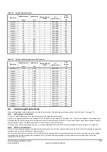
Page 20: ...Regen System considerations must be made for the additional ventilation requirements due to the introduction of the Regen and Switching Frequency filter inductors A Regen System can operate in an ambi...

Page 21: ...high frequency voltage comparable with the output voltage from a standard drive All precautions recommended for motor cables must also be applied to all cables connected to this DC circuit Drive size...

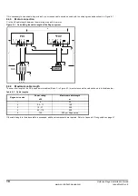
Page 22: ...em 6 4 4 Maximum cable length The sum total length of the DC bus and motor cables B and C in Figure 6 1 must not exceed the values shown in the table below Table 6 3 Cable lengths If the cable length...

Page 23: ...low from the supply into the drive Note that this latter effect is not an emission but it may be difficult to distinguish between incoming and outgoing harmonic current in a site measurement unless ac...

Page 24: ...average AC supply lines 0 5 30MHz 73dB V quasi peak 60dB V average EN61800 3 IEC1800 3 Product standard for adjustable speed power drive systems Input current 25A Requirements for the first environmen...

Page 25: ...stems to be constructed using numbers of drives with a single input stage or other more complex arrangements It is generally not possible to lay down specific EMC requirements for such systems since t...

Page 26: ...shows zero Total supply power of the drive is calculated from the product of the line voltage and current which is equivalent to 15 01 x 15 02 x 3 Note that as the power factor is approximately unity...

Page 27: ...age trip level Therefore it is best to use the default value of 700V unless the supply voltage is such that it must be raised above this level This parameter sets the PWM frequency and also determines...

Page 28: ...operate but the phase loss bit is set Heavy load the unit will detect mains loss disable itself and attempt to re synchronise When the Regen drive has powered up through the soft start resistor and th...

Page 29: ...rect gain settings can result in over voltage or over current trips The gain of the voltage controller is set by Pr 15 21 In most applications the default gains given for the current conditions will b...

Page 30: ...0V V is calculated from V 80V x motor voltage 400 x 700 DC bus voltage set point In some applications particularly with a high DC bus voltage set point and low switching frequency it may be necessary...

Page 31: ...gen sequencer Modulation 15 08 Switching frequency 15 09 High stability space vector modulation 15 10 Quasi square operation select Sequencer Menu 6 15 05 Supply frequency 15 06 Input inductance 15 03...

Page 32: ...ge and phase When it has been successfully synchronised to the line the DC bus voltage controller is enabled and the DC bus voltage rises to the target voltage Only when all of these stages have been...

Page 33: ...hen open loop vector operation is required the voltage mode should be set to UR_S Drive Enable Function Open loop only Pr 8 07 The default setting for terminal 30 in the open loop motoring drive is an...

Page 34: ...int However on the motoring drive the DC bus voltage remains relatively fixed with respect to ground As a result of the difference between the two voltages it is not possible to connect both drives to...

Page 35: ...k brake power could be 3 156A 400V 150 162kW This is much greater than the 22kW Regen drive is able to return to the supply hence a larger drive is required N If the Regen drive is not rated for the r...

Page 36: ...32 Unidrive Regen Installation Guide www controltechniques com Issue Number 2 Figure A 2 Power connections Single Regen Motor FS7 FS9 FS8 MCB1 aux 2 aux 3 Ovld...

Page 37: ...with the SKKD xxx F 12 or SKKE xxx F 12 diode modules The diode must be mounted on a suitable heatsink Heatsink sizing should be based on Maximum device case temperature of 80 C Power loss 2V x Regen...

Page 38: ...gital I O 3 27 Digital I P 1 28 Digital I P 2 29 Digital I P 3 30 Enable 31 0V Digital Motoring Drive 1 2 3 10V Out 4 0V Analog 5 Analog I P 1 6 Analog I P 1 7 Analog I P 2 8 Analog I P 3 9 Analog O P...

Page 39: ...settings It is very important that the Regen drive DC bus voltage set point is set above the peak AC supply voltage If this is not done then power will flow from the AC supply into the motoring drive...

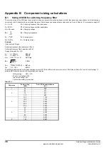
Page 40: ...ng time Ic Vc Zc Ic Charging current Example Unidrive size 5 Regen Switching frequency filter Inductance 100 H Switching frequency filter Capacitance 80 F Supply Voltage 480v 10 L 2 x 100 H 200 H C 3...

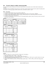
Page 41: ...wer dissipation in the resistor bank Irms 2 x R If the power dissipation exceeds the rating of the resistor bank add more resistors then go back to step 3 Table B 2 Table B 2 Table B 3 Table B 4 Table...

Page 42: ...ak current and charging time at power up with the trip being at for example 20 times the nominal rated current of the overload Therefore for a 20A peak current a 1A overload could be used The charging...

Page 43: ...er 4 time constants to ensure that the thermal trip area of the overload is not activated Refer to the following formula I at given Time Constant Exp 1 Time Constants x Ipeak The following example cal...

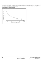
Page 44: ...rom this plotting the 10 times overload on Figure B 1 it can be seen that for a current of 11 10A when using a 1 6A breaker that the overload will trip at 7 x the nominal current 11 10 1 6 6 9 which e...

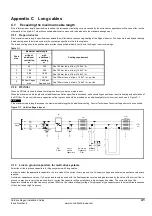
Page 45: ...e length with additional cooling Control Techniques Technical Support must be consulted Figure C 1 Unidrive Regen layout C 1 3 Line to ground capacitors for multi drive systems Selection of line to gr...

Page 46: ...at 3kHz switching frequency and a cable length of 1km motors DC has an IRMS of IRMS 4 85 x 10 4 kVDC l IRMS 4 85 x 10 4 x 2 x 620 x 1 000 IRMS 13 4A The IRMS is the total current line to ground theref...

Page 47: ...culations on page 36 for details For non standard systems components should be ordered independently Drive size CT kit Content of kit part number Varistors SS Resistor SFF Cap Soft Start O L 1 8070000...

Page 48: ...2A 26 7A UNI 3405 37kW 70A 56A 46A 35A 28A UNI 4401 45kW 96A 88A 70A UNI 4402 55kW 124A 104A 88A 70A UNI 4403 75kW 156A 124A 105A 80A UNI 4404 90kW 180A 175A 145A 110A UNI 4405 110kW 202A 175A 145A 11...

Page 49: ...200 180 215 12 4401 0001 1 5 5 12 5 00 200 180 215 14 4401 0002 1 7 5 16 3 75 240 180 270 17 4401 0003 1 11 25 2 40 240 180 270 24 4401 0004 2 15 34 1 76 320 220 325 32 4401 0005 2 18 5 40 1 50 320 22...

Page 50: ...om Issue Number 2 Figure F 2 Type 2 dimensions Figure F 3 Type 3 dimensions A2 B2 C2 A1 B1 C1 4 OFF 11 FIXING HOLE 11 HOLE PROJECTION SKOT TRANSFO RMER LTD COPYRIGHT C H L D 160 160 C L SKOT TRANSFORM...

Page 51: ...able F 2 Specifications Figure F 5 Resistor mounting bracket dimensions Table F 3 Resistor mounting bracket dimensions Drive size Resistance Diameter A Length B CT part number mm mm 1 2 150 19 1 73 12...

Page 52: ...capacitors size 1 and 2 Figure F 6 Dimensions Table F 4 Specifications Drive size CN x L Weight Mounting CT part number F mm kgs 1 2 3 x 5 7 53 x 116 0 3 M8 Stud 1610 5752 M8 to 53mm Fast on terminal...

Page 53: ...ensions Table F 5 Specifications Drive size CN d x h Weight Mounting CT part number F mm kgs 3 3 x 24 121 x 164 1 1 M12 Stud 1665 2244 4 3 x 48 121 x 164 1 5 M12 Stud 1665 2484 5 3 x 80 142 x 200 2 2...

Page 54: ...ve size 3 4 and 5 are supplied with the capacitor These should be fitted during installation as shown in Figure F 8 For Unidrive size 1 and 2 the discharge resistors are fitted internally to the capac...

Page 55: ...6 2 UNI 3402 40 0 750 60 180 160 190 12 4401 0167 2 UNI 3403 46 0 650 60 180 160 190 13 4401 0168 2 UNI 3404 60 0 500 80 240 160 255 16 4401 0169 2 UNI 3405 70 0 390 90 240 170 255 20 4401 0170 2 UNI...

Page 56: ...witching frequency filter inductor Type 3 Figure F 12 Switching frequency filter inductor Type 4 300 204 300 A2 B2 C2 100 A1 B1 C1 100 133 163 4 OFF S 10mm W 200 H L D 4 OFF 14 HOLES IN EACH FLAG 500...

Page 57: ...controltechniques com F 5 Varistors Figure F 13 Dimensions Table F 8 Specification Drive size Voltage Vac Energy J CT part number 1 to 5 550 400 2482 1501 1 to 5 680 450 2482 0680 1 Nom 6 21 max 34 m...

Page 58: ...tors 9 Inductors 10 Isolating transformer 33 K Kits 43 L Line to ground capacitors 41 Logic diagram 27 Long cables 41 M Magnetic overload 38 Magnetic overload sizing 38 Maximum cable length exceeding...

Reviews: