4
Unidrive Regen Installation Guide
www.controltechniques.com
Issue Number: 2
3
Power connections
The following section covers the power connections required for Unidrive Regen systems. Note that with Unidrive Regen systems there are no AC
supply connections made to L1, L2 or L3 drive terminals.
N
For control circuit connections refer to Chapter 4 Control circuit connections on page 8.
3.1
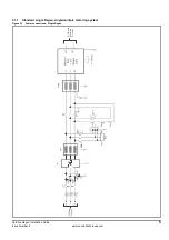
Overall system layout
The table below shows the key to the following system layout diagrams.
Table 3-1
Key to Figure 3-1 and Figure 3-2
E
Ground connection point
RFI
EMC filter
SFFL
Switching frequency filter inductor
L regx
Regen inductor
V1, V2, V3
Varistor network 550V (line to line)
V4, V5, V6
Varistor network 680V (line to ground)
Rsx
Softstart resistor
R-control
Ribbon cables to control pod (Unidrive size 5 only)
R-parallel
Ribbon cables between power modules (Unidrive size 5 only)
Fsx
AC supply fusing
Fx
AC Regen fusing (Unidrive size 5 only)
SFF Cx
Switching frequency filter capacitor
Rdx
Switching frequency filter capacitor discharge resistor
Tcx
Thermocouple
K1
Supply contactor
K2
Main contactor
K3
Auxiliary contactor
MCB1x
Switching frequency filter capacitor MCB
aux1x
Switching frequency filter MCB auxiliary through which Regen drive enable is
connected
aux2
Main contactor auxiliary for “main contactor closed signal”
aux3
K3 auxiliary with coil supply for K2
Ovld
Thermal, Magnetic overload
NOTE


