441-622-015
Type 500X
Page 4
3.1 Calibration
3.2.1
Zero and Span should always be checked after mounting. If unit is calibrated in a vertical position and
then mounted at an angle, readjustment of the zero is necessary. To calibrate use the following
procedure:
1. Open protective covers to expose zero and span adjustment screws.
2. Connect the recommended air supply to the inlet of the transducer and an accurate pressure
gage to the outlet.
3. Connect the electrical input and set the input signal to the minimum value of the range being
used (e.g., 4 mA for a 4-20 mA unit).
4. Observe the output pressure. If necessary, adjust zero screw until reaching minimum output
pressure setting. Turn zero screw counterclockwise to increase pressure, clockwise to
decrease pressure.
If unable to achieve output during calibration process, turn zero adjustment
screw counterclockwise for up to 30 revolutions, until output pressure rises.
5. Increase electrical input signal to its maximum value (e.g., 20 mA for a 4-20 mA unit).
6. Observe the output pressure. If necessary, adjust the span screw until reaching maximum output
pressure setting.
For I/P (current) input models turn span screw counterclockwise to increase
pressure, clockwise to decrease pressure. For E/P (voltage) input models turn
span screw clockwise to increase pressure, counterclockwise to decrease
pressure
.
7. The Zero and Span adjustments are interactive. After adjusting the span, it will be necessary to
recheck the zero. Repeat steps 3-6 until both end points are at the required values.
8.
For reverse acting
performance interchange the black and white electrical signal leads and carry
out the same input (4mA) to get maximum output then with maximum input (20mA) to get minimum
output. Repeat as necessary. FM Approvals approved units must be ordered per specific model code.
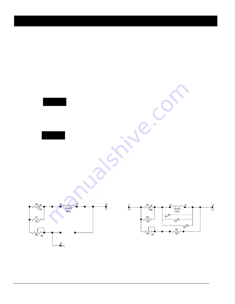
Figure 2
Electrical Schematic (E/P) Electrical Schematic (I/P)
3. OPERATION
NOTE
NOTE


