16
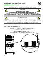
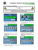
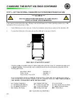
INSTALLATION CONTINUED
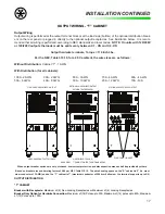
OUTPUT WIRING - “S” CABINET
Output Wiring
Output wiring is performed at the output terminal block or at the load side (bottom) of the optional distribution break-
ers on the rear panel or plugged in directly to the optional output receptacles. See Illustration below. It is recom-
mended that all wiring is performed according to NEC standards and local codes.
NOTE: On units with 120/208V
or 120/240V outputs the loads must be split evenly between X1 - XN and X2 - XN.
OUTPUT DISTRIBUTION
“S” CABINET
Breaker with Receptacle:
Maximum of (3) Non-Locking Receptacles, or Maximum of (4) Locking Receptacles.
Breaker Only Option for Hardwire Connection:
Maximum of (8) Poles up to 30A, Maximum of (6) Poles up to 60A,
Maximum of (12) poles up to 100A.
When output breaker options are not purchased, overcurrent protection and disconnection means shall be provided by others.
Based on breaker size and derating factor of 0.88 per NEC Table 310.16. The wire bending space on the “S” cabinet is 2” (i.e. maxi-
mum conductor of 3 AWG) and on the “T” cabinet is 7” (maximum conductor of 500 kcmil allowed – the terminal supports up to 2/0).
Per the NEC, Table 310.16, for a 40
°
C ambient, the wire sizes are as follows:
Without Distribution:
Cabinet “S” - 4 AWG
With Distribution (for all cabinets):
100A - 2 AWG
90A - 2 AWG
80A - 3 AWG
70A - 4 AWG
60A - 4 AWG
50A - 6 AWG,
40A - 8 AWG
30A - 10 AWG
20A - 12 AWG
15A - N/A
Output hardwire terminals, Torque = 110 Inch Lbs.
STANDARD HARDWIRED OUTPUT
OPTIONAL HARDWIRED OUTPUT
WITH OUTPUT BREAKERS
OPTIONAL RECEPTACLE OUTPUT
REAR VIEW - “S” CABINET OUTPUT CONFIGURATIONS
HARDWIRED OUTPUT TO LOADS
HARDWIRED TO LOAD
PLUG LOADS IN HERE
A
Summary of Contents for MODEL ES
Page 51: ...51 APPENDIX A RELATIVE DRAWINGS SCHEMATICS APPENDIX A ...
Page 57: ...57 NOTES ...


