35
OPERATION CONTINUED
INTELLISTAT TS
TM
MONITOR OPERATION
SYSTEM NORMAL
TIME: 07:58:17 AM
DATE: 03/31/10
X1
X2
LOW
BATTERY
CHARGE
LOAD %
MANUAL BYPASS
STATIC BYPASS
BATTERY
STATUS
INPUT
OUTPUT
PFC
LINK
INVERTER
PARAM
ALARMS
SETUP
TEST
ON/OFF
MAIN SCREEN
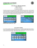
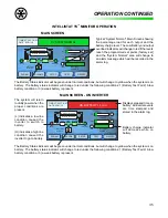
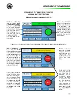
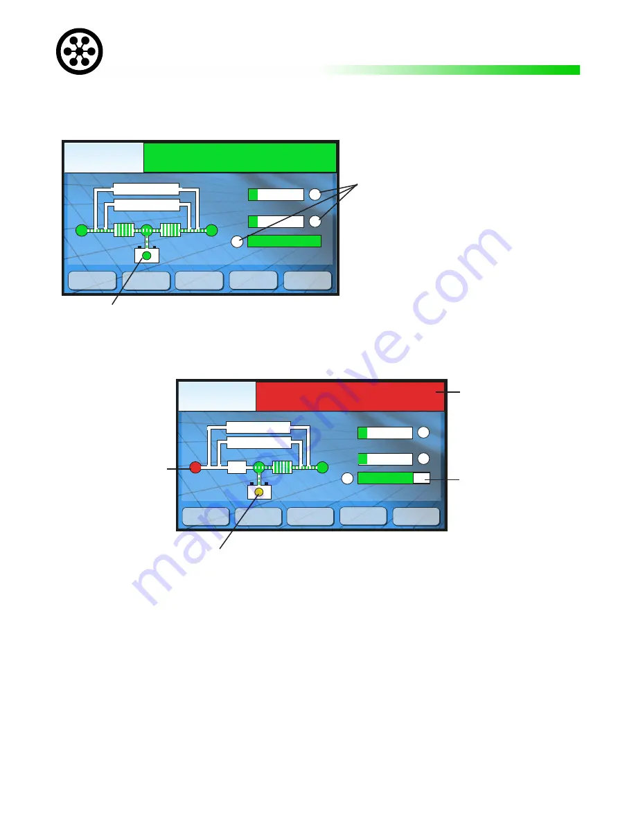
Typical “System Normal” Main Screen showing
the percentage load for each output and the
battery charge level. The Low Battery and output
overload indicators will change to red if the levels
reach the programmed set points (factory set)
and the “System Normal” area will change to
an alarm message which will be recorded in the
alarm log.
The Battery Status indicator will be green under normal conditions, but will change to yellow when the system is on
battery. The battery status indicator will change to red under the following conditions: 1) Battery Test Fail 2) A low
battery condition or 3) a weak battery is present.
ON BATTERY 1.4 min.
TIME: 07:58:17 AM
DATE: 03/31/10
X1
X2
LOW
BATTERY
CHARGE
LOAD %
MANUAL BYPASS
STATIC BYPASS
BATTERY
STATUS
INPUT
OUTPUT
PFC
LINK
INVERTER
L
PARAM
ALARMS
SETUP
TEST
ON/OFF
MAIN SCREEN - ON INVERTER
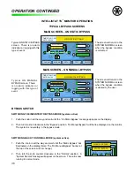
Displays elapsed time on
battery. All inverter events
are time stamped and
stored in the alarm log.
Battery charge indicator
will decrease while on
battery.
The system will return
to utility power when the
proper conditions are
present.
(L) Indicates a low line
condition caused the
inverter to switch to
battery.
(H) indicates a high line
condition caused the
inverter to go to battery.
The Battery Status indicator will be green under normal conditions, but will change to yellow when the system is on
battery. The battery status indicator will change to red under the following conditions: 1) Battery Test Fail 2) A low
battery condition or 3) a weak battery is present.
Summary of Contents for MODEL ES
Page 51: ...51 APPENDIX A RELATIVE DRAWINGS SCHEMATICS APPENDIX A ...
Page 57: ...57 NOTES ...

