background image

55

GB

L

E

K

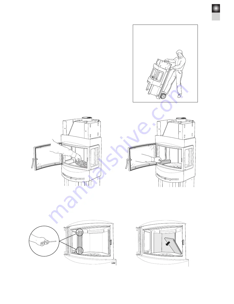
Lift and transport the stove 

as shown in these sketches.

Unpacking the stove

The cast-iron base may be removed to make it easie r to lift and 
carry the stove body.

Remove the cast-iron cover strips below the side windows.

Remove the grate disc by lifting the edge furthest away from the 
draught control bar.

Unscrew the metal brackets from the rear edge of the side win-
dows.

LEK

Remove the side bricks from the fire-box surround.

Summary of Contents for C 480

Page 1: ...C 480 www contura eu Installationsanvisning 2 Installationsanleitung 18 Installasjonsanvisning 34 Installation instruction 50 SE DE NO GB Installation instruction ...

Page 2: ... PERFORMANCE Essential characteristics Performance Harmonised technical specification Reaction to fire A1 WT Minimum distance to combustible material 100 mm to rear 494 mm to side Other safety distances according to the installation instructions Risk of falling embers Approved Emissions from combustion CO 0 12 NOx 25 mg m3 OGC 84 mg m3 PM 67 mg m3 Surface temperatures Approved Cleaning options App...

Page 3: ...d through these installation instructions carefully before installation Read how to best light your stove in the lighting instructions NOTE Report the installation of a stove to your local authority The owner of the house is personally responsible for ensuring compliance with the mandatory safety requirements and must have the installation approved by a qualified inspector Your local chimney sweep...

Page 4: ...a stove or erecting a chimney Before start ing installation work make sure that you check which regulations apply Structural support Check to make sure that the floor is strong enough to support the weight of the stove and chimney If you intend to locate the stove on standard wooden floor joists contact a professional builder to make sure that the construction will withstand the load If the total ...

Page 5: ... Fire retardant wall of brick or concrete 552 276 1250 Air inlet Ø64 Min 2100 to ceiling Combustible roof 100 240 100 240 312 452 395 535 855 715 Air inlet Ø64 Combustible wall 326 50 202 317 50 Air inlet Ø64 Fire retardant wall of brick or concrete 267 526 60 152 340 522 1191 1083 372 Tilluftsstos Ø64 Utv Ø150 A height from floor to chimney connection B height from floor to centre of hole for rea...

Page 6: ...permit the passage of an air supply hose Remove the partly punched metal cover with a hamme r 30 mm To prevent condensation in air ducts which pass through heated areas the duct must be insulated with 30 mm of mineral wool covered with a proprietary moisture seal plastic vapour diffusion retarder It is important to seal carefully around the duct where it passes through the wall or floor Use joint ...

Page 7: ...oved to make it easie r to lift and carry the stove body Remove the cast iron cover strips below the side windows Remove the grate disc by lifting the edge furthest away from the draught control bar Unscrew the metal brackets from the rear edge of the side win dows LEK Remove the side bricks from the fire box surround ...

Page 8: ... vermiculite holder IMPORTANT When correctly placed on top of the supporting pegs the baffle slopes upwards from the back to the front Lift the cast iron fire bed at one side and tilt it so that it can be removed through the door opening LEK Remove the rear brick from the fire box surround Stödtapp sida Vermiculitehållare LEK Side peg Vermiculiteholder ...

Page 9: ... be made in the wall for a rear flue connection Check the height to make sure that the hole aligns with the chimney connection on the rear of the stove Important When connecting the stove to a top flue make sure you fit the hot air vent and the screen before the chimney L E K L E K Gäller ej Make a hole at least 180 mm in diameter and then secure the flue collar in place in the wall using heat pro...

Page 10: ...cratch easily and may be marked by oil and grease Övre frontsten 403357 Nedre frontsten 403353 Nedre vänster sidosten 403355 Vänster toppsten 403361 Höger toppsten 403360 Övre sidosten 403358 Övre ryggsten 403359 Mellanryggsten 403362 Nedre ryggsten 403356 Nedre höger sidosten 403354 Left top stone 403361 Upper front stone 403357 Lower front stone 403353 Lower left side stone 403355 Lower right si...

Page 11: ...ve body on the base plate Slide the right and left hand side stones into place from the front Press the stone gently in towards the stove body to prevent it from being scratched by the side pieces Secure each stone with 4 screws M6x8 The side stone should fit flush with the front edge of the side piece ...

Page 12: ...to place Slide the upper front stone into place behind the upper front piece of the stove Take care not to damage the edge of the front piece Secure the upper front stone with 2 concrete screws Ø6x30 Do not tighten the screws fully until all the side stones have been fitted ...

Page 13: ...ce between the lower side stones and the metal panels Fit the front stone to the stove body with two socket head screws M5x12 All that is needed is a slight turn of the screws Place the six olivine blocks on top of the fire box as shown above Fit the screen top grille and top stones If the stove has a rear flue connection place the covering plate on top of the top grille NOTE If a fan is to be ins...

Page 14: ...he cable sheathing is potentially lethal If the event of any defect or malfunction return the fan to the place of purchase Screw the two rubber bushings in place on the fan bracket with two screws M6x8 Screw the fan bracket to the fan securing it with a nut and washer Screw the headless shank into place in the factory fitted nut until half of the thread has passed through Then fit the supporting f...

Page 15: ...e The fan s air outlet box should then press against the metal plate of the stove base IMPORTANT The sensor may only be fixed with the cable socket Damage to the cable sheathing is potentially lethal Operating instructions Plug the fan cable into the wall socket The control has eight positions Position 0 Off Positions 1 4 auto Four different speeds the fan starts stops automatically when the stove...

Page 16: ...e rear edge of the side window in place Unscrew the lugs along the top and bottom edges of the side win dow and then lift out the pane of glass Fit the brackets to the extra glass side panel Put the extra glass side panel in place and then refit the side win dow the metal retaining brackets and the cast iron cover strip Fitting an extra glass side panel optional extra ...

Page 17: ...e first pile of logs has burnt down stoke up the fire again by placing 3 or 4 logs weighing 2 2 5 kg in all on the embers Pulling out the grate shuttle lever opens the grate disc to allow ashes to be shaken down into the ash pan Note however that if the grate disc is open continuously while the stove is in use there is a risk that the stove and chimney may be damaged by overheating Important It is...

Page 18: ......

Page 19: ......

Page 20: ...B Box 134 SE 285 23 Markaryd Sweden www contura eu Contura reserves the right to change dimensions and procedures described in these instructions at any time without special notice The current edition can be downloaded from www contura eu ...

Reviews: