Operation Controls
and Functions
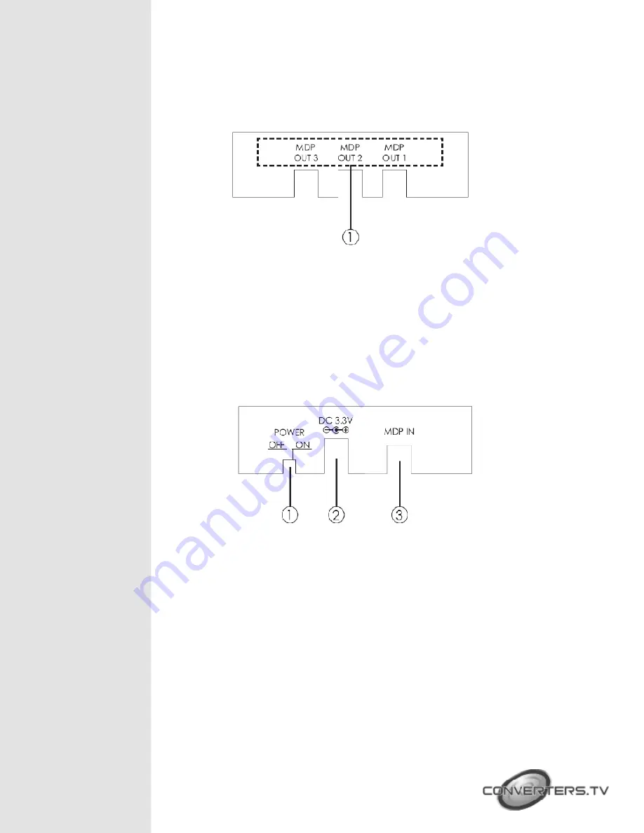
Front Panel
①
MDP OUT 1~3:
Connect these slots with the output displays Mini Display Port
input port in order to send a signal.
Note:
It is suggested to use the same type/model of display in order to
get optimal image quality. When the input source’s timing is matched with
the output display’s timing, the device will first extend the image according to
the specifications of the connected output display. If the input sources timing
does not match the output display’s timing the device will then split the signal
to match the number of the connected display to show an identical image.
(Detail information please refer to section 8. Timing table for monitors).
Rear Panel
①
On/off switch:
Push this switch to turn the device on or off. The green LED
will turn on when the device is switched on.
②
DC 3.3V:
This slot is where you plug the 3.3V DC power supply into the unit
and connect the adaptor to an AC outlet.
③
MDP IN:
This slot is where you connect the input source equipment such as
a PC or any output device that has a Mini Display Port.


