Product
Support Guide
water
witch
Electronic Water Leveller
09
•
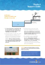
A TAP OR TWO-WAY VALVE MUST BE
PLACED BEFORE THE SOLENOID TO
ENABLE THE WATER SOURCE TO BE
TURNED OFF AT ANY TIME.
• Standard installation positions the supply
line 20mm above the fill balance line
without a hard connection (An air gap is
required to ensure the water from the
project cannot contaminate the water
source).
THE FILL FLOW RATE MUST
NOT EXCEED THE RATE THE BALANCE
LINE TRANSFERS WATER INTO THE
PROJECT.
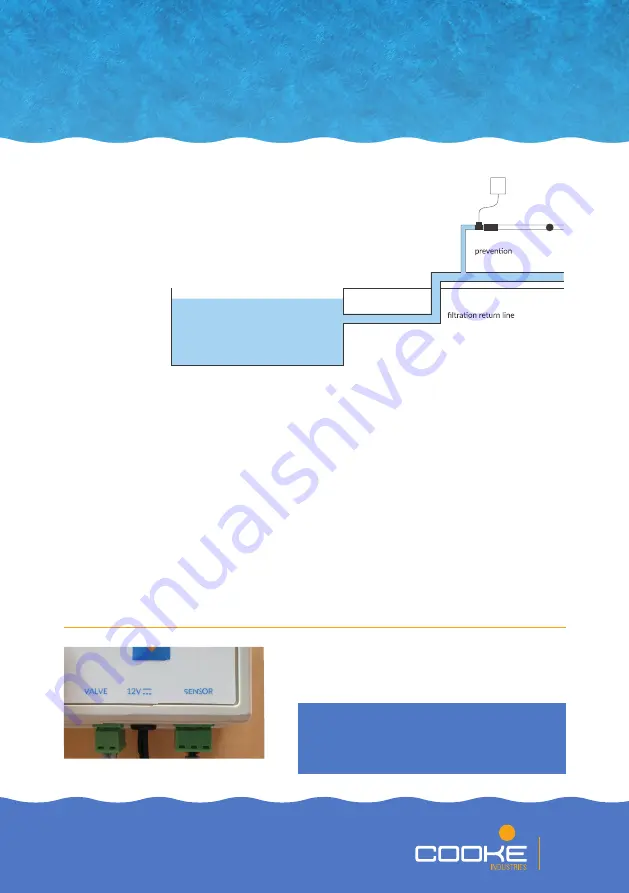
• If approved in your local area, the fill
line can be plumbed into the filtration
return line. If installing in this manner,
A
BACKFLOW PREVENTION VALVE MUST
BE INSTALLED BETWEEN THE SOLENOID
AND THE WATER SOURCE TAP.
• The solenoid requires an operating
pressure range of 29-116 PSI (200-
800 kPa).
ENSURE THE ONSITE
PRESSURE IS SUITABLE FOR CORRECT
OPERATION OF THE SOLENOID.
Install
a pressure limiting valve on the water
supply line if the onsite pressure is greater
than 116 PSI (800 kPa).
The solenoid is a wearing component with an
indefinite operating life. Your project should
include suitable overflow provision in case of
possible solenoid failure.
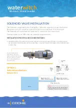
Solenoid &
backflow
valve
Tap or
Two-way
valve
Water source
Control
Box
40mm or 50mm
POOL
20mm
supply
line
NOTE:
Sensor and Solenoid plugs must face
backwards when inserted into the new Water
Witch Control Box.
OPTION 2
Solenoid installed into
filtration return line


