background image

Page 7

Fuse and mains plug replacement

This product is supplied with a fitted plug which
contains a 13A fuse. If you are simply replacing the
fuse, you must use a 13A fuse which has been
approved by ASTA to BS1362.

If the plug does not fit the socket or becomes
damaged, a new plug must be fitted. Replace the
original plug with the correct plug for your socket. If
this is a 3-pin (square pin) 13A (BS1363) plug, you
must make sure that it is fitted with an ASTA
approved 13A fuse.

If another type of plug is used, it must be protected
by a 15A fuse, either in the plug or at the
distribution board.

1. Cut off the existing fitted plug.

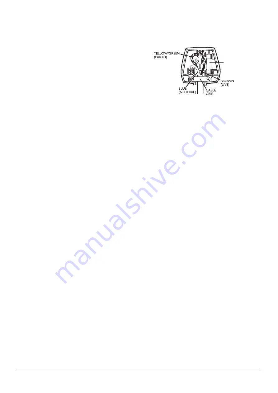
2. The wires in the mains lead supplied with this
appliance are coloured in accordance with the
following code (Figure 11):

GREEN/YELLOW = EARTH (E)     
BLUE = NEUTRAL (N)  BROWN = LIVE (L)

This product must be earthed

As the colours of the wires in the mains lead may
not correspond with the colour markings identifying
the terminals in your new plug, proceed as follows.

The wire which is coloured GREEN or
YELLOW/GREEN must be connected to the
terminal which is marked with the letter E or 

E

symbol or coloured GREEN or YELLOW/GREEN.

The wire which is coloured BLUE must be
connected to the terminal in the plug which is
marked with the letter N or coloured BLACK or
BLUE.

The wire which is coloured BROWN must be
connected to the terminal which is marked with the
letter L or coloured RED or BROWN.

3. Ensure that the connections are tight and that no
loose strands are left out of the terminals.

IF IN ANY DOUBT CONSULT A QUALIFIED
ELECTRICIAN.

If the mains lead becomes damaged consult a
qualified electrician.

FIGURE 11

FUSE

Summary of Contents for CZ51162

Page 1: ...SE ER R I IN NS ST TR RU UC CT TI IO ON NS S Please read these instructions carefully before using this product and keep them safe for future reference CZ51162 CZ51057 CZ51172 Larder fridge with work...

Page 2: ...ow the cooling gases to stabilise if transported in a horizontal position O Do install to allow for adequate ventilation around the appliance O Do not install near heaters or other heat sources O Do u...

Page 3: ...cooling and operation The minimum clearances are shown in Figure 2 Switching on Plug the appliance into a nearby power socket and switch on Open the door to reveal the temperature control Figure 1 th...

Page 4: ...et top Figure 6 Transfer the pivot plate to the mounting holes in the opposite corner of the underside of the cabinet top and fasten it in place with the screws removed earlier Prise the blanking plug...

Page 5: ...lvent based cleaners on any part of the appliance either internally or externally Drainage channel Water collects in the drainage channel on the back wall It then passes to a drip tray on top the comp...

Page 6: ...nblock hole of the fridge The motor is on for long Door opened too often Do not open door periods without switching off needlessly The airflow around the unit Allow more free space is inadequate aroun...

Page 7: ...the following code Figure 11 GREEN YELLOW EARTH E BLUE NEUTRAL N BROWN LIVE L This product must be earthed As the colours of the wires in the mains lead may not correspond with the colour markings id...

Page 8: ...panying the product the Crossed Out Wheelie Bin symbol indicates that this appliance fitting may not be treated as household waste Instead it shall be handed over to the applicable collection point fo...

Reviews: