102
www.cooperbussmann.com/wirelessresources
Cooper Bussmann 915U-2 Wireless Mesh I/O and Gateway User Manual
Rev Version 1.2.2
115S-11
115S-12
115S-13
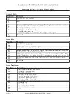
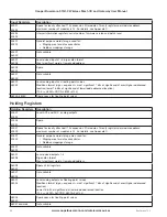
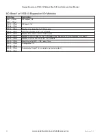
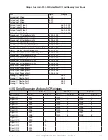
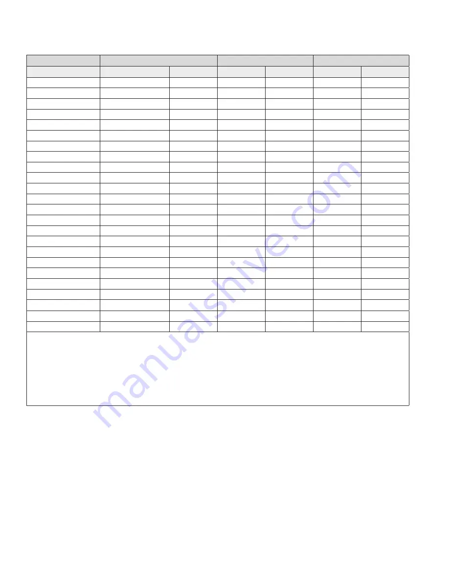
Description
Inputs
Outputs
Inputs
Outputs
Inputs
Outputs
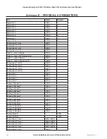
Digital I/O 15
10015
15
Digital I/O 16
10016
16
Analog I/O 1
30001
40001
Analog I/O 2
30002
40002
Analog I/O 3
30003
40003
Analog I/O 4
30004
40004
Analog I/O 5
30005
40005
Analog I/O 6
30006
40006
Analog I/O 7
30007
40007
Analog I/O 8
30008
40008
Pulsed I/O Count 1
30017-30018
30009
30009
30009
Pulsed I/O Count 2
30019-30020
30010
30010
30010
Pulsed I/O Count 3
30020-30022
30011
30011
30011
Pulsed I/O Count 4
30023-30024
30012
30012
30012
Pulsed I/O Count 5
30013
30013
30013
Pulsed I/O Count 6
30014
30014
30014
Pulsed I/O Count 7
30015
30015
30015
Pulsed I/O Count 8
30016
30016
30016
Pulsed I/O Rate 1
30001
Pulsed I/O Rate 2
30002
Pulsed I/O Rate 3
30003
Pulsed I/O Rate 4
30004
Supply Voltage
30033
30033
30033
Analog Loop Supply
30034
30034
30034
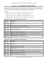
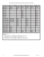
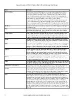
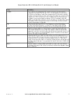
All expansion I/O is calculated by adding the offset to the I/O address in the table. The offset is calculated by multiplying the
module address by 20.
For example:
• Digital input #1 on an 115S-11 (address 5) would be: (5x20) + 10001 = 10100
• Digital output #2 on an 115S-11 (address 6) would be: (6x20) + 2 = 121
• Analog input #3 on an 115S-12 (address 3) would be: (3x20) + 30003 = 30063
• Analog output #7 on an 115S-13 (address 7) would be: (7x20) + 40007 = 40147

