20
www.cooperbussmann.com/wirelessresources
Cooper Bussmann 915U-2 Wireless Mesh I/O and Gateway User Manual
Rev Version 1.2.2
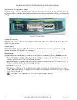
Side Access Configuration Panel
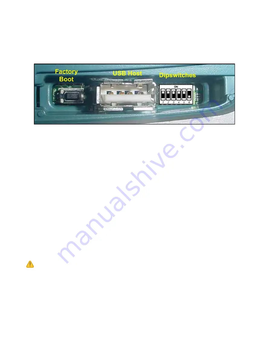
A small access panel on the side of the module hides a factory boot switch, USB host port, and a small bank of
DIP switches that are used for analog input voltage and current selection, external boot, and default configuration
settings.
Figure 11 Access Panel
Factory Boot Switch
The factory boot switch is used for factory setup and diagnostics. This switch should only be used if advised by
ELPRO technical support.
USB Host Port
This port is a USB host (master port) that can interface with USB storage devices for upgrading the module
firmware. For details, see “System Tools” on page 74.
DIP Switches
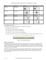
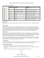
The DIP switches are used to select a number of functions within the module, as shown in the following table.
•
DIP switches 1 to 2
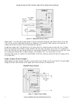
—Used for measuring current or voltage on analog input 3. Set DIP switches to “on” to
measure current (0–20 mA) and “off” for voltage (0–5 Vdc).
•
DIP switches 3 to 4
—Used for measuring current or voltage on analog input 4. Set DIP switches to “on” to
measure current (0–20 mA) and “off” for voltage (0–5 Vdc).
•
DIP switch 5
—Not used.
•
DIP switch 6
—When set to “on” (enabled) and the module is restarted, the module boots up with a known
factory default configuration, including a default IP address for the Ethernet connection. See “4.1 Connecting
to the Module” on page 32.
NOTE When DIP switch 6 is “on,” radio and I/O functionality is disabled.

