www.cooperbussmann.com/wirelessresources
Cooper Bussmann 915U-2 Wireless Mesh I/O and Gateway User Manual
27
Rev Version 1.2.2
C
hapTEr
3 - OpEraTION
3.1 Overview
The 915U-2 Series I/O modules are designed to provide standard off-the-shelf telemetry functions at an economic
price. Telemetry is the transmission of data or signals over a long distance via radio or twisted-pair wire cable.
3.2 LED Indicators
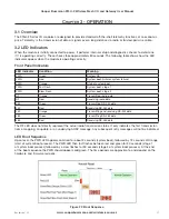
When the module is initially connected to power, it performs internal setup and diagnostics checks to determine
if it is operating correctly. These checks take approximately 80 seconds. The following table shows how the LED
indicators appear when the module is operating correctly.
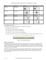
Front Panel Indicators
LED Indicator
Condition
Meaning
PWR
Green
System OK
PWR
Red
System boot (initial or system failure)
PWR
Orange
Start of system boot
PWR
Fast Flash
System boot, stage 1
PWR
Slow Flash
System boot, stage 2
RF
Orange
Transmitting radio data
RF
Red
Receiving radio data
232
Green
Transmitting RS
-
232 data
232
Red
Receiving RS
-
232 data
232
Orange
Transmitting and receiving RS
-
232 data
485
Green
Transmitting RS
-
485 data
485
Red
Receiving RS
-
485 data
The RF LED does not directly represent the actual radio transmission status. It only indicates the first transmission
from a mapping, an update, or an underlying AODV message. Any subsequent retry messages will not be indicated.
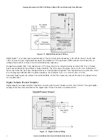
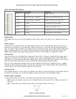
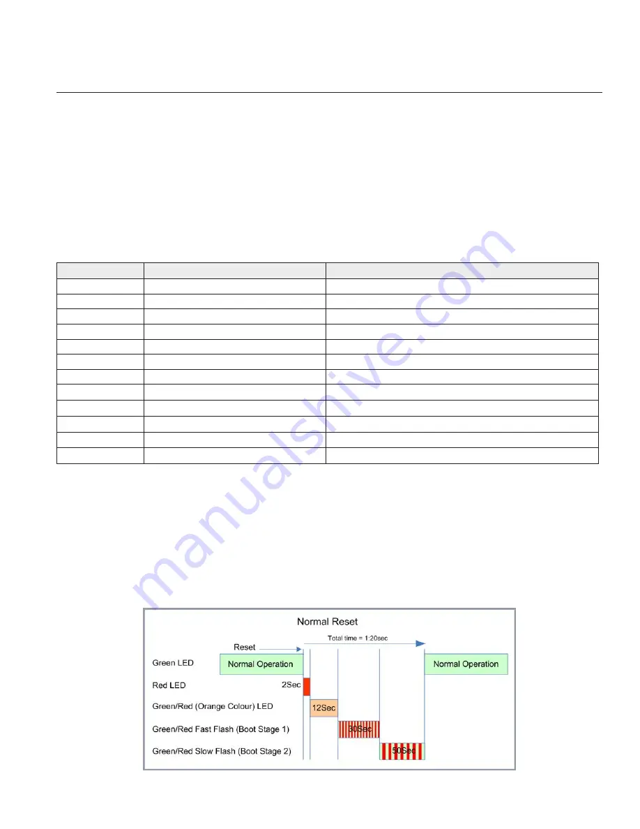
LED Boot Sequence
Upon reset, the PWR LED appears solid red for about 2 seconds (system boot), followed by 12 seconds of Orange
(start of system boot process). The PWR LED then fast flashes between red and green for 30 seconds (stage 1
of system boot process) followed by a slow flashes for 50 seconds (stage 2 of system boot process). At the end
of the boot sequence the PWR should appear solid green. The time periods are approximate, and depend on the
hardware and firmware revisions.
Figure 22 Boot Sequence

