www.cooperbussmann.com/wirelessresources
Cooper Bussmann 915U-2 Wireless Mesh I/O and Gateway User Manual
47
Rev Version 1.2.2
Common I/O Registers for the 915U-2
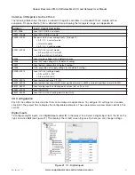
The following table shows the basic on-board I/O registers available in a standard 915U-2 module with no
expansion I/O connected to it. For a detailed I/O map showing the full register range, see Appendix B.
Address
Input / Output Description
0001–0008
Local DIO1–DIO8, as outputs
10001–10008
Local DIO1–DIO8, as inputs
10009–10020
Set point status from analog inputs 1 through 12:
• AI1, 2, 3, 4 current mode
• Internal supplies
• AI1, 2, 3, 4 voltage mode
30001–30004
Local AI1–AI4 (current mode):
• AI1 and AI2, 4–20 mA diff
• AI3 and AI4, 4–20 mA sink
30005
Local supply voltage (0–40V default scaling)
30006
Local 24V loop voltage (0–40V default scaling)
30007
Local battery voltage (0–40V default scaling)
30008
115S expansion I/O supply voltage (0–40V default scaling)
30009–30012
Local AI1–AI4 (voltage mode):
• AI1and AI2, 0–20V
• AI3 and AI4, 0–5V
30013–30016
Local pulse input rates PI1–PI4
36001–36008
Local pulsed input counts (PI1 most significant word is 36001 and least significant word is 36002)
38001–38032
Local analog inputs as floating point values (mA, volts, or Hz)
40001–40002
Local AO1–AO2
48001–48002
Local AO1–AO2 as floating point values (mA)
I/O Configuration
Each I/O has different characteristics that can be tailored to applications. To configure I/O settings for a module,
click
I/O
in the project tree to display the configurable parameters. These parameters are described in detail in this
section.
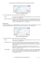
Digital Inputs
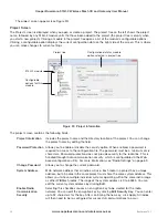
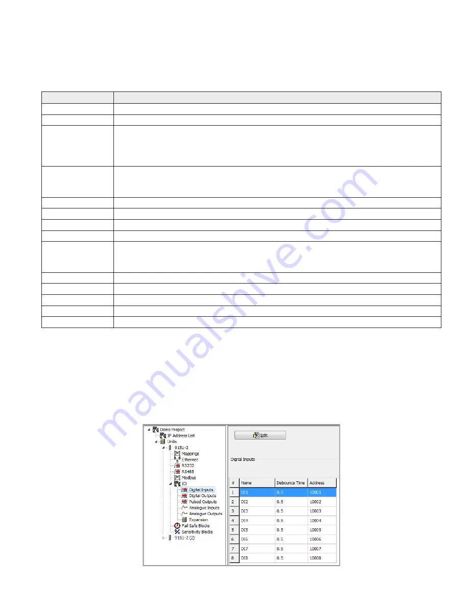
To configure digital inputs, click
Digital Inputs
under
IO
in the project tree. Select a digital input from the list on the
right, and click
Edit
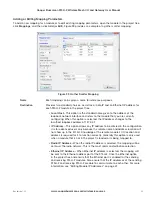
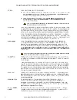
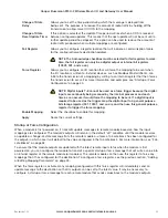
(see Figure 41). This displays the IO Edit screen (Figure 42) where you can change settings.
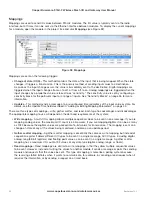
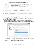
Figure 41 IO - Digital Inputs

