www.cooperbussmann.com/wirelessresources
Cooper Bussmann 915U-2 Wireless Mesh I/O and Gateway User Manual
55
Rev Version 1.2.2
Invalid Register State
All registers within the module can have different states, depending on the type of register and the type of value it
holds. A typical analog range is between 0 and 65535, and a digital can be 0 or 1. Registers that are not associated
with a physical I/O can also be in the “invalid” state, which means that the register has not been written to and
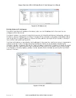
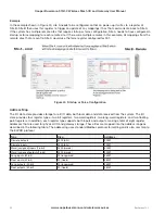
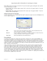
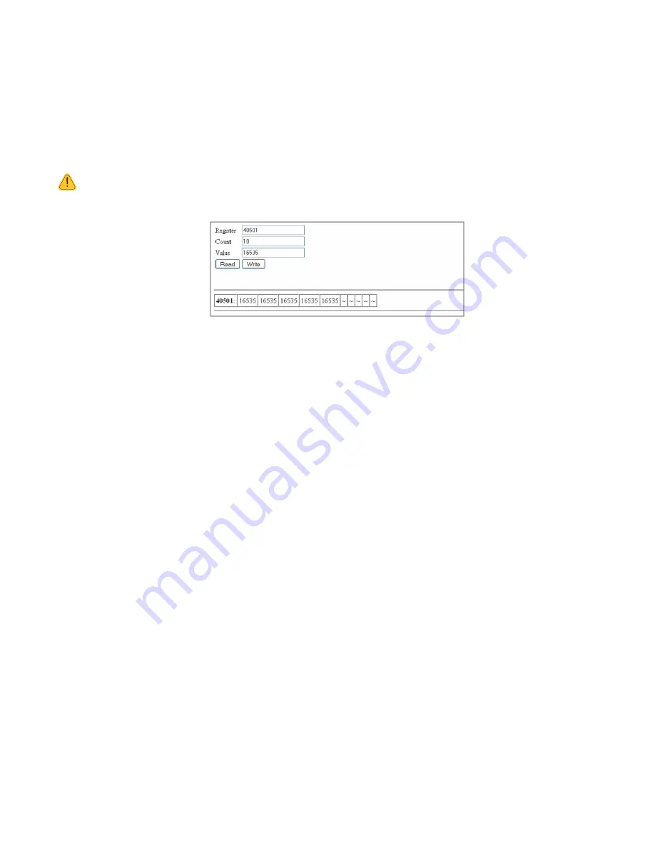
holds a non-value or null value. For example, if you use I/O diagnostics to read the registers, an invalid register
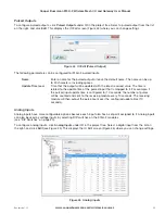
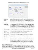
would read “~“ as shown in Figure 52. For information on I/O diagnostics, see Chapter 5.
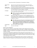
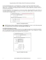
NOTE Any mapping with an invalid register will be inhibited from sending. This is to ensure that the data
sent to the destination is valid and not the default values the module has on startup. See “Fail-safe Blocks”
on page 53 for information on configuring registers with a valid value at startup.
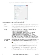
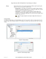
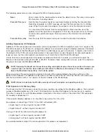
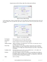
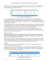
Figure 52 Invalid Register State
Sensitivity Blocks
All registers have a configurable sensitivity value that determines how much the register needs to change before a
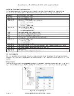
change-of-state” (COS) message is sent. All registers except the following have a default sensitivity value of 1:
• The 12 analog inputs have a sensitivity of 1000 bits, or approximately 3% (1000 bits from a total range of
32768 = 3.05%).
• The 24 floating point values have a default sensitivity of 0.5 units.
• Inputs 38001–38004 will be 0.5 mA, inputs 38005–38012 will be in volts, and inputs 38013–38016 will be in
hertz.
A sensitivity value is needed for analog inputs in order to prevent the module from sending every single-bit change
of an analog value, and subsequently saturating the radio channel with unwanted COS messages. If a lower
sensitivity is required, the sensitivity block can be adjusted. However, care should be taken to not reduce the
sensitivity to the point where radio messages are so frequent (due to a sensitivity change) that it saturates the radio
network. There is a fine line between adjusting system parameters to receive up-to-date data and overloading the
radio communications. A total of 50 sensitivity blocks can be configured for different registers or different values.
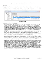
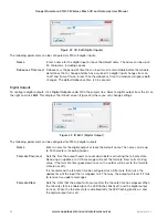
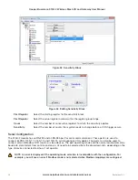
To change sensitivity blocks for a module, click
Sensitivity Blocks
in the project tree (see Figure 53). The screen
lists existing sensitivity blocks for this module. To add a new sensitivity block, click
Add
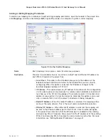
. To edit an existing
sensitivity block, select it in list on the right, and click
Edit
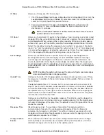
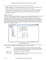
. This displays the IO Edit screen (see Figure 54) where
you can change settings. To delete a sensitivity block, select it in the list and click
Delete
.

