72
www.cooperbussmann.com/wirelessresources
Cooper Bussmann 915U-2 Wireless Mesh I/O and Gateway User Manual
Rev Version 1.2.2
Example #1
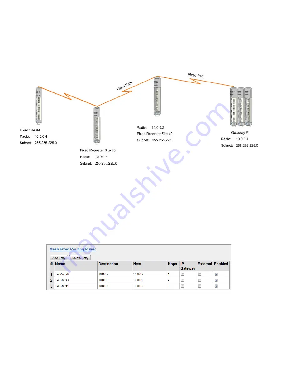
Normally, a meshing network will learn the routing paths within the network and set up a communication pathway
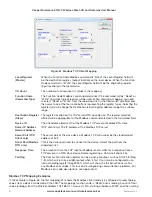
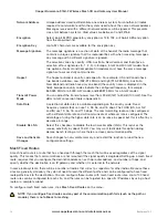
to the destination, but some instances require you to create a fixed radio path. The network diagram in Figure 72
shows a basic network where the remote sites (#2, #3, and #4) all need to communicate back to Site #1 using fixed
route paths rather than automatically meshing and finding their own path.
Figure 72 Mesh Fixed Route #1
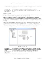
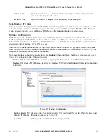
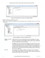
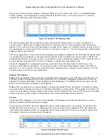
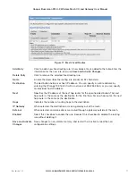
Figure 73 shows the mesh fixed routing rules in the gateway for the network diagram in Figure 72. Entry #1 shows
the destination IP address will be 10.0.0.2 (Repeater Site #2) and its next address will be itself (10.0.0.2). It is only
one hop, and the ”IP Gateway” and “External” checkboxes are deselected because the destination will be the local
I/O on 10.0.0.2.
Entry #2 is similar to entry #1, except the destination address is 10.0.0.3 and the number of hops is two. The next
address is 10.0.0.2 because all communications will pass through Repeater Site #2.
Entry #3 is also similar to entries #1 and 2, except the destination address is 10.0.0.4 and the number of hops
is three. The next address will be the same as the other two routes because all communications will pass
through 10.0.0.2.
Figure 73 Mesh Fixed Route - Gateway
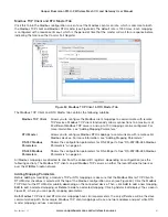
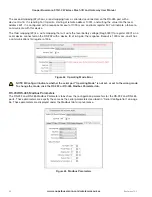
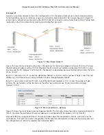
Figure 74 shows the mesh fixed routes for Repeater Site #2. The first entry shows the communication path back to
Site #1, therefore the destination IP and next address are configured with the address 10.0.0.1 (Site #1).
Because Site #2 is a repeater for Site #4, the second route shows the destination as Site #4, with Site #3 as the
next address. The mesh fixed route configurations for the other remote modems will have similar routing rules, but
the configuration will reflect the required communication paths.

