www.cooperbussmann.com/wirelessresources
Cooper Bussmann 915U-2 Wireless Mesh I/O and Gateway User Manual
81
Rev Version 1.2.2
Watchdog Error Log
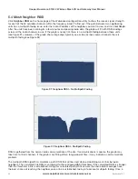
The module uses a various processes to control aspects of its internal functions, such as radio operation, I/O
functionality, AODV communications, and Modbus communications. Each process runs independently, and can
interact with the other processes to provide a robust wireless I/O product.
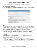
All processes are monitored by an internal “watchdog.” If a processes has a problem and stops running, the
watchdog will identify the problem and restart the process. The watchdog also creates a text file showing which
process had the problem. This text file is stored in a directory called ”dog” off the main root IP address of the
module. To display this text file in your browser, enter http://XXX.XXX.XXX.XXX/dog/, where XXX.XXX.XXX.XXX is
the IP address of the module.
If the watchdog directory continues to show text files, it may indicate a problem with the module or its
configuration. If this happens, save the module configuration (see “System Tools” on page 74) and the list of
watchdog files, and then contact ELPRO technical support.
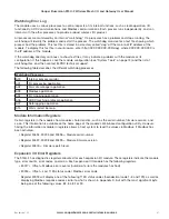
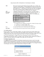
The following table describes the different watchdog processes.
Watchdog Processes
A00
Internal process monitor
A01
I/O processing application
A02
Fail-safe manager application
A03
Modbus application
A04
I/O mapping application
A06
AODV meshing protocol application
A07
Data logging application
A15
Warm restart backup
Module Information Registers
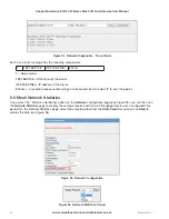
Certain registers in the module show modules characteristics, such as the serial number, firmware version, and
so on. This information is available on the home page of the module’s Web-based configuration utility. However,
having the information available in registers allows a host system to read the values via Modbus, if Modbus has
been activated.
• Register 30494, 30495 and 30496 = Module serial number
• Register 30497, 30498 and 30499 = Module firmware version
• Register 30500 = Firmware patch level
Expansion I/O Error Registers
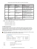
The 915U-2 has diagnostics registers allocated for each expansion I/O module. These registers indicate the module
type, error counts, error codes, and so on. Each expansion I/O module has the following registers.
• 30017 + Offset = Modbus error counter (number of errors the modules has had)
• 30018 + Offset = Last 115S status code / Modbus error code
Register 30018 will display one of the following 115S status codes (hexadecimal code 1–5 and 129), as well as
displaying Modbus response codes similar to what is shown in Appendix D, but with the most significant byte
being one of the following values, 82, 84, 8F or 90.

