background image

Connecting Low Voltage Inputs

The LiteKeeper-8

®

 logic board can support up to 64 switch 

inputs. Of these 64 inputs, 8 of them may be dry contact clo-

sure inputs that are connected to the terminal blocks on the 

left side of the LiteKeeper

®

 Logic Board. Digital switch inputs 

may also be used on the LiteKeeper

®

. If no contact input type 

switches are being used, the full 64 switch inputs may consist 

of digital switches. If a combination of contact input switches 

and digital switches are being used, the combined total cannot 

exceed 64 inputs.
Regardless of input type used, it is recommended that all in-

put wiring be done prior to applying power to the logic board. 

Please verify that there are no shorts to AC Ground prior to 

connection of input devices.
Regardless of input type, the following notes apply.
1.  All low voltage wiring is Class 2 wiring.
2.  All low voltage wiring must enter the cabinet into the Low 

  Voltage section of the enclosure. Low Voltage wiring can be  

  brought into the enclosure from the left side of the enclosure.  

  Failure to separate high voltage from low voltage wiring  

  may cause interference with logic board function.
3.  All low voltage wiring must be run in separate conduit from  

  line-voltage wiring.
4.  Test all low voltage wiring for shorts to AC ground before  

  connection to the relay panel.
5.  When powering peripheral devices such as motion sen- 

  sors and photocells from the LiteKeeper

®

 panel, there may  

  be a limitation on the number of sensors that can be sup- 

  ported. This is also true if digital switches are used with the  

  system. See the recommendations below or contact Cooper  

  Controls for further information.
6.  It is recommended that power be removed from the logic  

  board when doing initial switch input wiring.

Contact Input Switch Wiring

This section describes the wiring for dry contact closure de-

vices. There are eight switch input wiring terminals on the left 

side of the LiteKeeper-8

®

 to allow for wiring of the dry contact 

closure devices. 
1.  Use 18 AWG twisted, unshielded wire for all low voltage  

  dry contact closure device wiring.
2.  Maximum length for dry contact closure device wiring is  

  1000 feet.
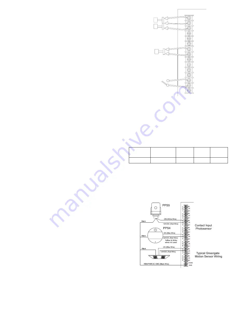
3.  Please see wiring detail below for details on connections  

  of different devices to the LiteKeeper-8

®

 system.


LiteKeeper-8

®

 Low Voltage Switch Wiring

Contact Input Photosensor and Greengate Sensor Notes

It is possible to use a contact input photosensor and Greengate 

Motion Sensors in conjunction with the lighting control system. 

The LiteKeeper-8

®

 is capable of powering a number of these 

devices. Please refer to the chart below for details on how 

many devices the transformer can support. 

Please contact technical support if it is necessary to power 

additional sensors beyond the numbers listed above. These 

figures do not account for additional devices such as digital 

switches being used. If using a combination of devices, please 

contact technical support for exact limits on how the number 

of devices the logic panel can power.

             Photocell and Motion Sensor Wiring

ON
+24VDC
OFF

Momentary

Maintained

OFF

+24VDC

ON

ON
+24VDC
OFF

OFF

+24VDC

ON

ON
+24VDC
OFF

Toggle

C

H

1

C

H

2

C

H

3

C

H

4

C

H

5

40

16

20

20

Greengate

PIR Sensor

Greengate 

Dual-Technology

Sensor

Greengate

Ultrasonic

Sensor

PPS-4

Indoor

Photosensor

4

PPS-5

Outdoor

Photosensor

Page 5

Summary of Contents for Greengate LiteKeeper-8

Page 1: ...nly as intended and at the listed voltage 5 All installation service must be performed by qualified personnel or service technicians 6 Install in accordance with National Electrical Code and any other codes that may apply 7 High Voltage is present inside the lighting enclosure Use extreme caution when performing maintenance on this equipment Failure to follow this warning and proper safety procedu...

Page 2: ...istency 3 Tighten down relay terminal screws Manufacturer s recom mended torque rating is 7 lbs in 0 59 lbs foot 0 8 Nm 4 Document relay to circuit information for future reference Standard Relay Card Wiring Latching Relay Card Notes 1 The Latching Relay Card is rated for single pole load use only Connection of 2 pole circuits loads to the Latching Relay Card will void the equipment warranty and m...

Page 3: ...tched state for a period of 30 seconds After 30 seconds the relay will assume its programmed state 5 During a power outage the LRM relay will remain in the state it was in prior to the power outage Once power re turns the relay will stay in its state for 30 seconds then assume its programmed state 6 There is a manual switch on each relay that indicates relay status and allows for a temporary overr...

Page 4: ...80V A Single Pole Relay is also available rated at 347V All relays are rated to 20 Amps The following information describes the installation of the relays onto the Two Pole Relay Card Each Two Pole Relay Card has eight mounting clips for the placement of the relays The Two Pole Relay Card will hold eight 208V Two Pole Relays one in each mounting clip The 480V Two Pole Relay uses two mounting clips...

Page 5: ...th the system See the recommendations below or contact Cooper Controls for further information 6 It is recommended that power be removed from the logic board when doing initial switch input wiring Contact Input Switch Wiring This section describes the wiring for dry contact closure de vices There are eight switch input wiring terminals on the left side of the LiteKeeper 8 to allow for wiring of th...

Page 6: ...red using the Cooper LCCP or LCCNP cable or Belden 1502P or 1502R equivallents For best network performance one of the suggested cables should be used If the specified cable is not used and com munications problems occur that require troubleshooting assistance additional charges for support may be assessed Digital Switch devices should be networked together in a daisy chain configuration No T Taps...

Page 7: ... refer to Programming Guide that came with the unit to program via the keypad or to your Keeper Enterprise Manual for programming details It is recommended that a Clear Settings Command be performed on the controller before the first programming is done to clear any test data that may be left in the controller from factory testing Repair Information If a repair becomes necessary on your LiteKeeper...

Page 8: ...ation or misapplication by damage during shipment or by improper service There are no warranties which extend beyond the hereinabove limited warranty INCLUDING BUT NOT LIMITED TO THE IMPLIED WARRANTY OF MERCHANTABILITY AND THE IMPLIED WARRANTY OF FITNESS No employee agent dealer or other person is authorized to give any warranties on behalf of the Seller or to assume for the Seller any other liabi...

Reviews: