Networking
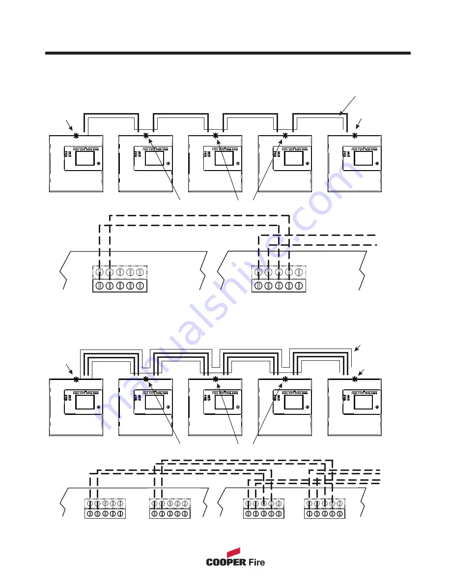
Network Cable
2 Cores
Network 1
Cable
Network 1
Cable
Network 1
Cable
Network 1
Cable
Terminator
fitted
Terminator
fitted
Terminator not required
Terminator not required
Wiring Diagram
Next
Next
Terminator
fitted
Terminator
fitted
Screened
cable
Screened
cable
Network Cable
2 Cores
Network Cable
2 Cores
Network Cable
2 Cores
Please Note: Cooper Network cards are fitted with loop terminators as standard please cut if not required.
Daisy chain configuration
Single Network Card
Redundant Network
TOP
TOP
TOP
B
B
B
X
X
X
E
E
E
Y
Y
Y
A
A
A
TOP
TOP
B
B
X
X
E
E
Repeater Panel
Network 1 Terminal
on main PCB
Repeater Panel
Network 1 Terminal
on main PCB
Repeater Panel
Network 2 Terminal
on main PCB
Y
Y
A
A
Main Panel
Network Terminal
on main PCB
Main Panel
Network 1 Terminal
on main PCB
Main Panel
Network 2 Terminal
on main PCB
15
Repeater Panel
Repeater Panel
Panel 1
Panel 1
Panel 2
Panel 2
Panel 3
Panel 3
Panel 4
Panel 4
Network 2
Cable
Network 2
Cable
Network 2
Cable
Network 2
Cable
Summary of Contents for CTPR3000
Page 4: ...Contents ...
Page 5: ...Contents Contents Page ...
Page 6: ...System Installation and Design Section 1 6 ...
Page 16: ...Commissioning Section 2 16 ...
Page 18: ...Panel Controls Indicators Section 3 18 ...
Page 50: ...Appendix Section 4 50 ...


