background image

3

COOPER LIGHTING SOLUTIONS    

 IB514101EN 


 Installation instructions

Installation Instructions – LAS Area / Site

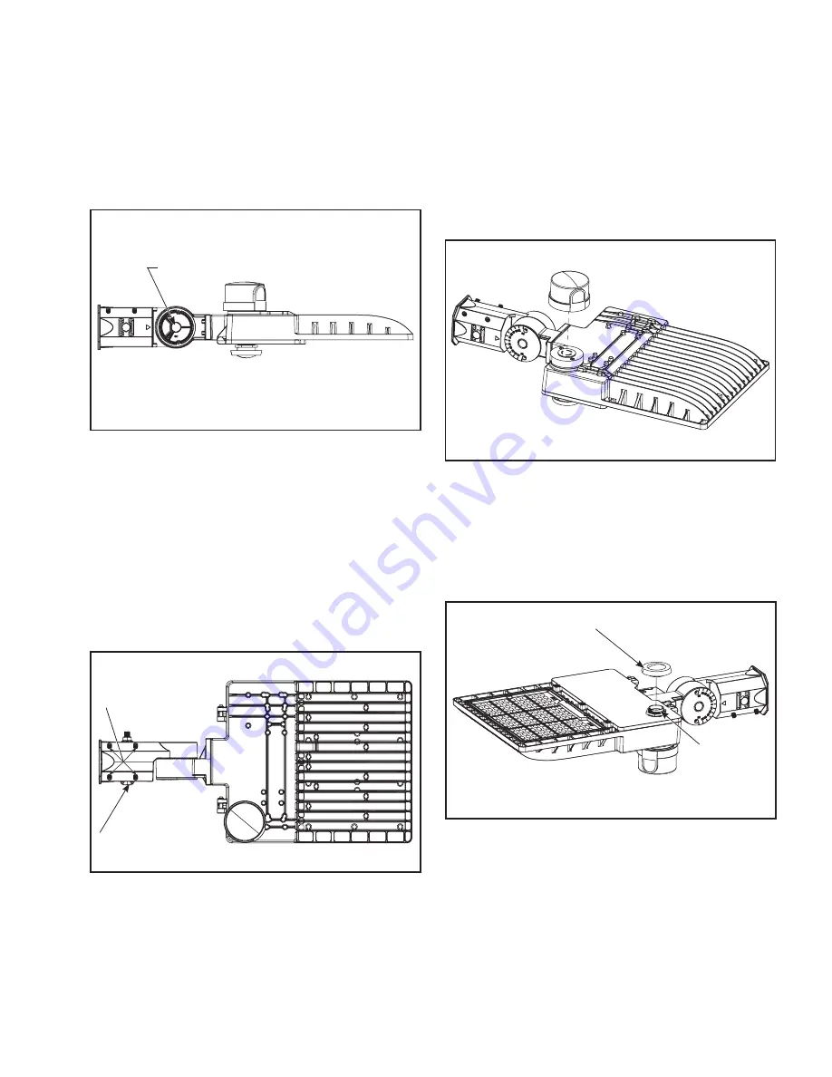
Figure 4.   

Figure 5.   

Figure 6.   

Hex Head Bolt

Motion Sensor Lens

Motion Sensor 

Receptacle

Allen Head Screws 

Through bolt

3.  Adjust slipfitter to the desired angle by loosening the 

center hex bolt enough to rotate and adjust. Retighten 

the center hex bolt to 120 in-lbs. to secure. (Figure 4.)

ote: 

N

Fixture suitable for down mount only. Do not tilt 

above 45 degrees from horizontal.

4.  Reinstall slipfitter cover plate via two Phillips head 

screws. (Figure 2.)

5.  Connect luminaire to supply wires:

a.  Connect supply side line voltage to black lead.
b.  Connect supply side neutral wire to white lead.
c.  Connect supply side ground wire to green lead.

6.  Remove the slipfitter through bolt and install slipfitter 

onto 2-3/8” O.D. tenon. Be careful not to pinch any 

wires and tighten the four Allen head set screws to 30 

in-lbs. (Figure 5.)

7.  If mounting to a horizontal tenon, reinstall the through 

bolt to secure fixture to tenon. Tighten through bolt to 

120 in-lbs. (Figure 5.)

PHOTOCONTROL / SHORTING CAP INSTALLATION 

1.  Insert provided photocontrol (or shorting cap) into the 

receptacle and twist into locked position. (Figure 6.)

MOTION SENSOR LENS INSTALLATION  

(IF APPLICABLE)

1.  Remove the clear plastic cap that covers the motion 

sensor receptacle on the fixture.

2.  Twist to install the provided motion sensor lens onto 

receptacle until secure. (Figure 7.)

Figure 7.   

Summary of Contents for Lumark LAS Area/Site

Page 1: ...user s purpose please contact your nearest representative ote N Care must be taken not to set lighting fixture down on optical lenses or lift the fixture in the lens area ote N Specifications and dime...

Page 2: ...00 18 100 8 4 900 8 300 9 4 900 8 300 Allen Head Screws 2 Using the provided small flat head screwdriver adjust the selectable lumen switch to the desired light level Nominal lumens in table below For...

Page 3: ...voltage to black lead b Connect supply side neutral wire to white lead c Connect supply side ground wire to green lead 6 Remove the slipfitter through bolt and install slipfitter onto 2 3 8 O D tenon...

Page 4: ...ctrique de coupure ou d autres accidents de personne L installation et l entretien de ce produit doivent tre effectu s par un lectricien qualifi Ce produit doit tre install conform ment aux r gles d i...

Page 5: ...ournevis t te plate fourni r glez l interrupteur de s lection de lumens l intensit de lumens d sir e Flux lumineux nominal indiqu dans le tableau ci dessous Pour une valeur sp cifique par distribution...

Page 6: ...T CIRCUIT 1 Ins rez l interrupteur photo lectrique ou fiche de mise en court circuit dans le r ceptacle et tournez le pour le verrouiller en place Figure 6 4 R installez le couvre joint de l adaptateu...

Page 7: ...ento de este producto deben ser realizados por un electricista calificado Una persona con conocimientos sobre la construcci n y el funcionamiento del producto y los riesgos implicados debe instalar es...

Page 8: ...nillos de cabeza Allen 2 Con el destornillador peque o de cabeza plana provisto ajuste el interruptor de selecci n de l menes al nivel deseado de iluminaci n Encontrar los l menes nominales en la tabl...

Page 9: ...movimiento Recept culo de sensor de movimiento Tornillos de cabeza Allen Perno pasante Figura 7 4 Vuelva a instalar la placa de la cubierta del adaptador deslizante con dos tornillos de cabeza Phillip...

Page 10: ...Cet quipement a t mis l essai et d clar conforme aux limites tablies pour un dispositif num rique de cat gorie A en vertu de l article 15 des r glements de la FCC Ces limites sont con ues pour assure...

Reviews: