P82623 F
Sheet 4 of 6
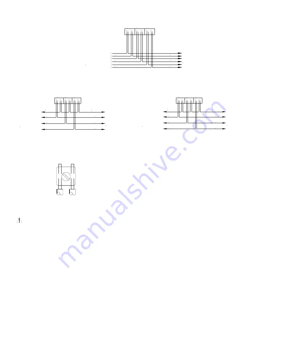
Supervised System
(+)
(-)
TO NEXT APPLIANCE
OR END OF LINE
RESISTOR (EOLR)
FROM PRECEDING
APPLIANCE OR
FIRE ALARM CONTROL
PANEL (FACP)
PRI 1
PRI 2
(-)
(+)
PRI 3
(-)
(+)
PRI 1
PRI 2
PRI 3
PRI 3
PRI 2
PRI 1
Isolated inputs are provided for independent supervision and actuation of the three audible inputs.
Unsupervised System
Common Positive
Unsupervised System
Common Negative
(+)
(-)
PRI 1
PRI 2
(-)
(+)
PRI 3
(-)
(+)
PRI 1
PRI 2
PRI 3
PRI 3
PRI 2
PRI 1
POSITIVE
COMMON
COMMON
POSITIVE
FROM PRECEDING
APPLIANCE OR
FIRE ALARM CONTROL
PANEL (FACP)
TO NEXT APPLIANCE
OR END OF LINE
RESISTOR (EOLR)
(+)
(-)
PRI 1
PRI 2
(-)
(+)
PRI 3
(-)
(+)
PRI 1
PRI 2
PRI 3
PRI 3
PRI 2
PRI 1
NEGATIVE
COMMON
COMMON
NEGATIVE
FROM PRECEDING
APPLIANCE OR
FIRE ALARM CONTROL
PANEL (FACP)
TO NEXT APPLIANCE
OR END OF LINE
RESISTOR (EOLR)
For applications not requiring supervision: connect all positive (+)
terminals to the power source. The negative (-) terminal for each
appliance will actuate the appliance.
For applications not requiring supervision: connect all negative (-)
terminals to the power source. The positive (+) terminal for each appliance
will actuate the appliance.
In case of simultaneous inputs, the three audible outputs are self-prioritized as follows: 1st priortiy= PRI 1; 2nd priority = PRI 2; 3rd priority = PRI 3.
Leave any unused inputs disconnected.
1.
AMT Multitone appliance models have in-out wiring terminals that
accept two #12 to #18 American Wire Gauge (AWG) wires at each
screw terminal. Strip leads 3/8 inches and connect to screw
terminals.
2.
Break all in-out wire runs on supervised circuits to assure integrity of
circuit supervision as shown on left. The polarity shown in the
wiring diagrams is for operation of the appliances. The polarity is
reversed by the FACP during supervision.
NOTE:
Wiring method shall be in accordance with CSA C22.1, Canadian Electrical Code, Part 1, Safety Standard for Electrical Installations, Section 32.
MOUNTING PROCEDURES:
CAUTION:
If sheated multiconductor cable or 3/4" conduit fittings are used, check that installed product has sufficient clearance and wiring room
prior to installing backboxes and conduit.
1. AMT Multitone Appliances can be flush mounted to a standard 4 inch square by 2-1/8 inch deep electrical box (Figure A) or a standard 2-gang by 2-
1/2 inch minimum deep electrical box (Figure B).
2. Select largest backbox shown in Mounting Options where possible, to provide additional wiring room for easy installation.
3. Conduit entrance to backboxes should be selected to insure sufficient wiring clearance for installed equipment. When extension rings are required,
conduit should enter through backbox, not extension ring. Use Steel City #53151/1-1/2" deep or #53171/2-1/8" deep extension rings or equal with
same area cut out in back.
4. The AMT-12/24 model can also be surface mounted to Cooper Notification's Indoor/Outdoor Backbox (Model IOB) for indoor/outdoor use (Figure C).
5. The AMT-12/24 model is supplied with four snap-in covers to hide the mounting holes and provide an attractive installation. The snap-in covers are
interchangeable and have slots on each end so they can be removed if necessary (by prying them up with a thin blade screwdriver). To insert snap-
in cover, slide one side partially into mounting hole recess; align the cover so that snap-in cover and grille are parallel to each other (not tilted) and
snap cover into place.
6. The IOB surface backbox has 1/2 inch conduit knockouts on two sides. It has a variety of knockouts on the back for mounting it to recessed
electrical boxes and for wire entrances (Figure D). It can also be mounted to a surface with the two mounting ears that are supplied. The ears slide
into slots on the back of the box. Use appropriate anchors for the wood screws that are supplied with the box (if necessary).
7.
For outdoor use, the IOB includes a prefastened gasket and four hole plugs. Use the mounting ears to secure the box (do not use the back
knockouts). Use the hole plugs to seal the unused mounting holes on the AMT Multitone grille (press them in securely from the back side of the
grille). Mount the unit to the IOB with the four #8-18 screws supplied with the box.
8.
All models are UL Listed for indoor and outdoor use with a temperature range of -40
o
F to +150
o
F (-40
o
C to +66
o
C) and maximum humidity of 98%
2% RH.
MOUNTING OPTIONS:


