15
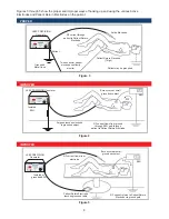
7 . Insert the Active Electrode into the Active Electrode Socket on the top right side of the LEEP PRECISION
Generator’s front panel . Either the Hand Switch-Operated Electrode (Pencil) or the Foot Switch-Operated
Electrode (Pencil) may be used .
8 . Insert the selected Electrode (Needle, Loop, Square or Ball) into the Active Electrode .
9 . Set the ON/OFF switch to ON . A red indicator lamp on the console (R/F ON) will indicate that the hold
mode has been initialized . After Self-Check, the SYSTEM READY LED (green) will illuminate .
7
4
4
NOTES
If the LEEP PRECISION system does not cycle to the SYSTEM READY status and a series of prolonged
audible beeps are heard, turn the system off and check for faulty hand, foot, or panel switches . See the
TROUBLESHOOTING section (page 22, Section G) of this manual for additional information .
Do not be alarmed if the LEEP PRECISION Smoke Evacuator turns on at this point. This is the
unit cycling
.
10 . Ensure patient is connected securely to the Patient Return Electrode before beginning .
WARNING
POSITIVE CONTACT MUST BE COMPLETE BETWEEN THE PATIENT AND THE PATIENT RETURN
ELECTRODE. IF NOT, SEVERE BURNING OF TISSUE MAY RESULT. THE ENTIRE AREA OF THE
PATIENT RETURN ELECTRODE SHOULD BE RELIABILY ATTACHED TO THE PATIENT’S BODY
AND AS CLOSE TO THE OPERATING FIELD AS POSSIBLE.
11 . The output is selected by the mode selector buttons . When a mode is selected, the intensity should be set
by depressing the RAISE ( b) or LOWER ( c) button . If either CUT (pure cut/blended cut) or COAG
mode is selected and the Foot Switch is depressed, the output will be active . When the Foot Switch or Active
Electrode is actuated, the R/F ON lamp will illuminate and the beeper will emit a pulsing tone .
12 . The LEEP PRECISION Generator is ready for use and the SYSTEM READY LED (green) will illuminate .
If the operator feels the output of power is not sufficient, the Patient Return Electrode should be checked to
see that good contact is made with the patient before increasing the power setting .
13 .
CROSS CONTROL:
The sequence of operation of the LEEP PRECISION Generator is nonpreferential; that
is, either the Foot Switch (pedal) or the Hand Switch will activate the output (providing all safety measures
are met) . The Foot Switch and the Hand Switch cannot be operated simultaneously .
1
1
4
4
IMPORTANT
If using the Foot Switch, the button on the front panel must be used to control the OUTPUT mode . When
the COAG mode ( g) is selected on the front panel, the CUT or BLEND modes cannot be invoked by the
Hand Switch (yellow) Button . The CUT mode, if desired, must be selected on the front panel and then
invoked either by the Hand Switch- or the Foot Switch-operated pencil .
1
WARNING
Positive contact must be complete between the patient and the Patient Return Electrode . If a Split/Dual
Patient Return Electrode is not securely affixed to the patient, the PATIENT PAD LOOSE indicator LED (red)
will indicate an improper return path . The PATIENT PAD LOOSE safety circuitry disables the output when an
unsafe condition occurs in the Patient Return Electrode circuit . Poor connections or insufficient contact area can
cause R/F burns . The entire area of the Patient Return Electrode should be reliability attached to the patient’s
body and as close to the operating field as possible . Use only approved CooperSurgical LEEP PRECISION
Dual/Split Patient Return Electrodes . Do not use a single (not split) Patient Return Electrode as it may cause
severe tissue burns in the vicinity of the Patient Return Electrode .
4
Summary of Contents for LEEP PRECISION LP-20-120
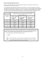
Page 24: ...24 CUT mode 16 1 Power Output Characteristics ...
Page 25: ...25 CUT mode BLEND mode COAG mode 16 2 Power Output at Various Load Resistance ...
Page 52: ...52 16 1 Eigenschaften der Ausgangsleistung ...
Page 53: ...53 16 2 Leistung bei variablem Lastwiderstand ...
Page 80: ...80 16 1 Características de la potencia de salida ...
Page 81: ...81 16 2 Potencia de salida con diferentes resistencias de carga ...
Page 108: ...108 16 1 Caractéristiques de sortie de puissance ...
Page 109: ...109 16 2 Sortie de puissance à résistance de charge variable ...
Page 136: ...136 16 1 Caratteristiche della potenza in uscita ...
Page 137: ...137 16 2 Potenza in uscita a diverse resistenze di carico ...
Page 164: ...164 16 1 Características de potência de saída ...
Page 165: ...165 16 2 Potência de saída a várias resistências de carga ...
Page 192: ...192 16 1 功率輸出特徵 ...
Page 193: ...193 16 2 各種負載電阻下的功率輸出 ...
Page 199: ...Notes Notizen Notas Notes Note Notas 備註 198 ...


