30
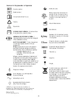
Section 19 Explanation of Symbols
Reorder number
Serial number
Consult instructions for use
Dangerous Voltage
DEFIBRILLATOR PROOF SYMBOL
=
indicates that the device will not be damaged
if the defibrillator is active .
BF-TYPE EQUIPMENT
= Type of equipment
is a B-Type equipment with an F-Type
applied part .
B-Type
equipment is a piece of equipment
providing a particular degree of protection
against electric shock, particularly regarding:
- Allowable leakage current
- Reliability; of the protective earth
connection .
F-Type
= Isolated applied part . Applied part
isolated from all other parts of the equipment
to such a degree that the patient leakage
current allowable in single fault condition is not
exceeded when a voltage equals to 1 .1 times
the highest rated mains voltage is applied
between the applied part and earth .
APPLIED PART SYMBOL
= Electrode that
is connected to a patient’s body .
Medical equipment with respect to
electrical shock, fire and mechani-
cal hazard only in accordance with
UL60601-1 and CAN/CSA C22 .2
No .601 .1
6D33
SN
REF
Caution:
U .S . Federal law restricts
this device to sale by or on the order
of a physician .
R
x
Only
Fuse, Replace only with Specified
Type and Ratings
Alternating Current
Date of Manufacture
Equipotentiality Symbol (wires
carry the same voltage)
Manufacturer
Caution
!
Product conforms to the Medical
Device Directive 93/42/EEC
EC REP
Authorized Representative in
the European Community
NON
STERILE
Non-sterile
Earth (Ground)
Littelfuse® is a registered trademark of Littelfuse, Inc .
Bussmann
®
is a registered trademark of Cooper Industries, Inc .
LEEP PRECISION
™
is a trademark of CooperSurgical, Inc .
Made in the USA
© 2017 CooperSurgical, Inc .
Fragile
This side up
Keep Dry
In order to preserve, protect and
improve the quality of the
environment, protect human health
and utilize natural resources prudently
and rationally – do not dispose of
waste electrical or electronic
equipment (WEEE) as unsorted
municipal waste . Contact local WEEE
disposal sites .
Summary of Contents for LEEP PRECISION LP-20-120
Page 24: ...24 CUT mode 16 1 Power Output Characteristics ...
Page 25: ...25 CUT mode BLEND mode COAG mode 16 2 Power Output at Various Load Resistance ...
Page 52: ...52 16 1 Eigenschaften der Ausgangsleistung ...
Page 53: ...53 16 2 Leistung bei variablem Lastwiderstand ...
Page 80: ...80 16 1 Características de la potencia de salida ...
Page 81: ...81 16 2 Potencia de salida con diferentes resistencias de carga ...
Page 108: ...108 16 1 Caractéristiques de sortie de puissance ...
Page 109: ...109 16 2 Sortie de puissance à résistance de charge variable ...
Page 136: ...136 16 1 Caratteristiche della potenza in uscita ...
Page 137: ...137 16 2 Potenza in uscita a diverse resistenze di carico ...
Page 164: ...164 16 1 Características de potência de saída ...
Page 165: ...165 16 2 Potência de saída a várias resistências de carga ...
Page 192: ...192 16 1 功率輸出特徵 ...
Page 193: ...193 16 2 各種負載電阻下的功率輸出 ...
Page 199: ...Notes Notizen Notas Notes Note Notas 備註 198 ...

