
273 Branchport Avenue
Long
Branch,
NJ
07740
Thank you for using our products.
(800)
631-2148
(US)
INSTALLATION INSTRUCTIONS
www.cooperwheelock.com
SERIES NS-24MCC/MCCH MULTI-CANDELA HORN/STROBE
(CEILING MOUNT VERSION)
Use this product according to this instruction manual. Please keep this instruction manual for future reference.
GENERAL:
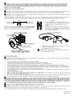
Cooper Wheelock’s Series NS Multi-Candela ceiling mount Horn/Strobe (NS) requires only 2-wires for operation of the horn and strobe circuits and provides either
four or two selectable candela settings (15, 30, 75, 95 or 115, 117). The NS is the ideal choice for applications where the audible silence feature is required. The NS is
UL Listed under Standard 1971 for Signaling Devices for the Hearing Impaired and UL Standard 464 for Audible Signal Appliances for
indoor use only
. It is molded
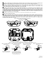
with a mounting plate for use with a 4” backbox or 100mm European backbox (See Figure A and mounting procedures). This strobe model is Listed for
ceiling
mounting only
. The NS uses a xenon flashtube with solid state circuitry enclosed in a polycarbonate lens to provide maximum visibility and reliability for effective
visible signaling.
The horn portion of the NS can be field set to provide either Continuous Horn or Code 3 Horn and can be field set for High (HI) or Low (LO) dBA.
NOTE:
The Code 3 temporal pattern (1/2 second on, 1/2 second off, 1/2 second on, 1/2 second off, 1/2 second on, 1-1/2 off and repeat) is specified by ANSI and
NFPA 72 for standard emergency evacuation signaling.
The Code 3 Horn should be used only for fire evacuation signaling and not for any other purpose.
The NS Horn/Strobe can be used with a Sync Module (SM), Dual Sync Module (DSM) or Wheelock power supplies to provide synchronized strobe and synchronized
Code 3 signal.
The NS Horn/Strobe is designed for use with either filtered DC (VDC) or unfiltered full-wave-rectified (VRMS) input voltage. All inputs are polarized for
compatibility with standard reverse polarity supervision of circuit wiring by a fire alarm control panel (FACP).
WARNING: PLEASE READ THESE INSTRUCTIONS CAREFULLY. FAILURE TO COMPLY WITH ANY OF THE FOLLOWING
INSTRUCTIONS, CAUTIONS AND WARNINGS COULD RESULT IN IMPROPER APPLICATION, CANDELA SETTING, INSTALLATION AND/OR
OPERATION OF THESE PRODUCTS IN AN EMERGENCY SITUATION, WHICH COULD RESULT IN PROPERTY DAMAGE AND SERIOUS
INJURY OR DEATH TO YOU AND/OR OTHERS.
SPECIFICATIONS:
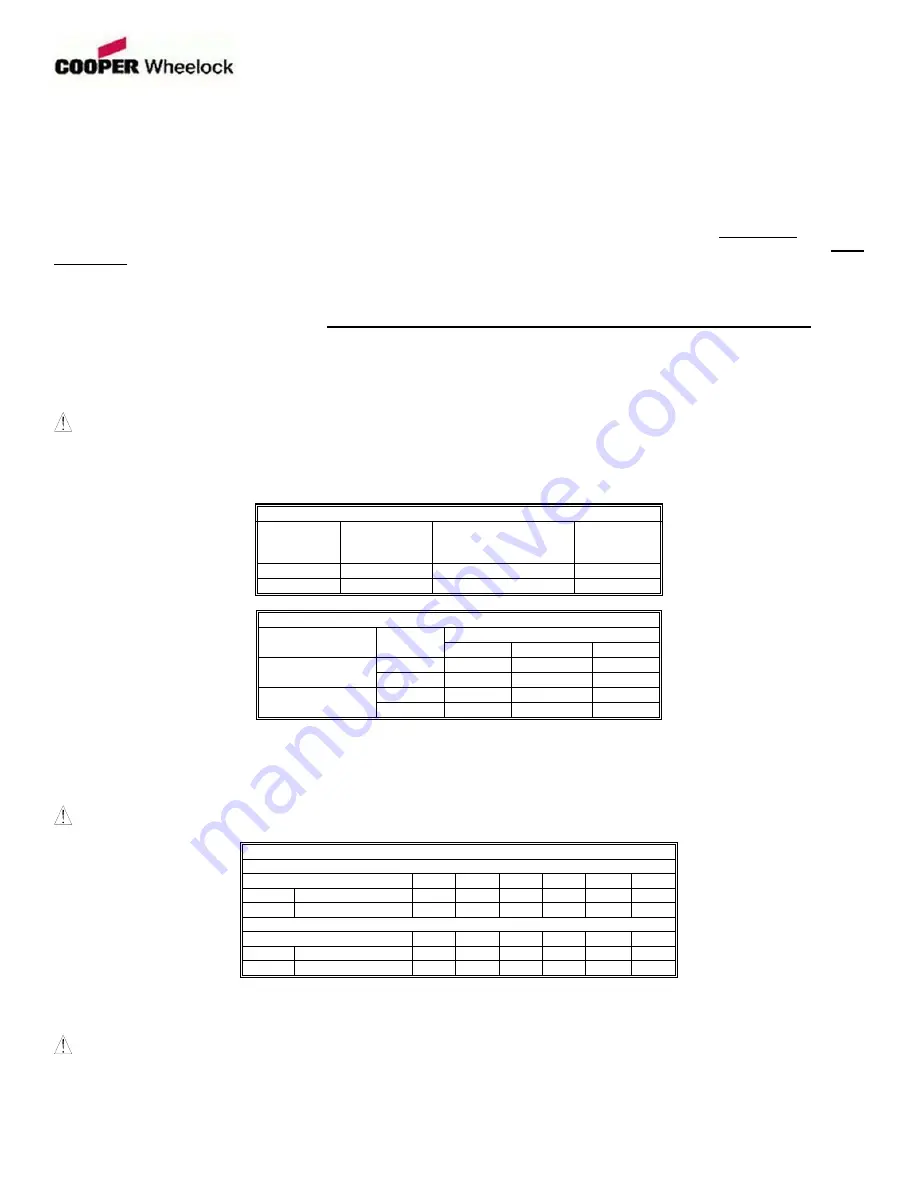
Table 1: UL Listed Models and Ratings
Model Regulated
Voltage
(VDC/VRMS)
Voltage Range Limit
Per UL 464 and UL 1971
(VDC/VRMS)
Strobe
Candela
(cd)
NS-24MCC 24
16.0-33.0 15/30/75/95
NS-24MCCH 24
16.0-33.0
115/177
Table 2: dBA Sound Output for 24VDC Per UL
Description
Volume
Reverberant dBA Per UL 464
16.0VDC
24.0VDC
33.0VDC
Low
78
81
84
Continuous Horn
High
84
88
90
Low
73
77
79
Code 3 Horn
High
80
83
85
NOTES:
1. The strobe will produce 1 flash per second over the "Regulated Voltage" range.
2. This horn/strobe model meets the required light distribution patterns defined in UL 1971.
3. All models are UL Listed for indoor ceiling use with a temperature range of +32
°
F to +120
°
F (0
°
C to +49
°
C) and maximum humidity of 93%
±
2% RH. The
effect of shipping and storage temperatures shall not adversely affect the performance of the appliance when it is stored in the original cartons and not subjected to
misuse or abuse.
WARNING: CANDELA SETTING WILL DETERMINE THE CURRENT DRAW OF THE PRODUCT.
Table 3: UL Current Ratings (AMPS)
Maximum RMS Current with Hi dBA Setting
Regulated Voltage
15cd
30cd 75cd 95cd 115cd 177cd
DC
16.0-33.0VDC 0.082 0.124 0.209 0.275 0.350 0.477
FWR
16.0-33.0VRMS 0.141 0.204 0.312 0.411 0.491 0.681
Maximum RMS Current with Low dBA Setting
Regulated Voltage
15cd
30cd 75cd 95cd 115cd 177cd
DC
16.0-33.0VDC 0.071 0.114 0.201 0.261 0.306 0.429
FWR
16.0-33.0VRMS 0.124 0.184 0.301 0.397 0.469 0.659
When calculating the total current: Use Table 3 to determine the highest value of “RMS Current” for an individual NS then multiply the value by the total number of
NS Appliances. Be sure to add the currents for any other appliances powered by the same source and to include any required safety factors.
NOTE:
The maximum number of strobes on a single notification appliance circuit shall not exceed 50.
CAUTION:
These notification appliances are UL Listed as “Regulated”. They are intended to be used with FACPs whose notification circuits are UL Listed as
“Regulated.” These appliances shall not be used on UL Listed “Special Application” notification circuits unless the appliances are identified to be compatible in the
installation instructions of the FACP or unless the FACP is identified to be compatible in this instruction manual.
Copyright 2006 Cooper Wheelock, Inc. All rights reserved.
P84794 F
Sheet 1 of 4


