
WARNING: THE NS APPLIANCE MUST BE FIELD SET TO THE DESIRED TONE AND dBA SOUND OUTPUT LEVEL BEFORE THEY ARE
INSTALLED. THIS IS DONE BY PROPERLY INSERTING JUMPER PLUGS IN ACCORDANCE WITH THESE INSTRUCTIONS. INCORRECT
SETTINGS WILL RESULT IN IMPROPER PERFORMANCE, WHICH COULD RESULT IN PROPERTY DAMAGE AND SERIOUS INJURY OR
DEATH TO YOU AND/OR OTHERS.
WIRING AND MOUNTING INFORMATION:
CAUTION:
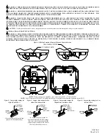
The following figure (A) shows the maximum number of field wires (conductors) that can enter the backbox used with each mounting option. If these
limits are exceeded, there may be insufficient space in the backbox to accommodate the field wires and stresses from the wires could damage the product.
CAUTION:
Check that the installed product will have sufficient clearance and wiring room prior to installing backboxes and conduit, especially if sheathed
multiconductor cable or 3/4" conduit fittings are used.
Although the limits shown comply with the National Electrical Code (NEC), Cooper Wheelock recommends use of the largest backbox option shown and the use of
approved stranded field wires, whenever possible, to provide additional wiring room for easy installation and minimum stress on the product from wiring.
Figure 6:
Figure 7:
OR END OF LINE
FROM PRECEDING
APPLIANCE, FACP
TO NEXT SIGNAL
+
-
RESISTOR (EOLR)
OR SYNC MODULE
When the sync module is used, the audible tone will be the
code 3 sound only
.
Refer to Sync Module installation instruction sheets for SM (P83123), DSM
(P83177) or Wheelock’s Power Supplies for additional information.
•
The NS Appliance has in-out wiring terminals that accepts two
#12 to #18 American Wire Gauge (AWG) wires at each screw
terminal. Strip leads 3/8” inches for connection to screw
terminals.
•
Break all in-out wire runs on supervised circuit supervision as
shown in Figure 7. The polarity shown in the wiring diagrams
is for the operation of the appliances. The polarity is reversed
by the FACP during supervision.
Figure 8: Cover Removal
Figure A: Flush Mounting
4" SQ X 2-1/8" BACKBOX
OR 100mmSQ x 37.5mm
COVER
#8-32 SCREWS
MOUNTING PLATE
ALIGN COVER OPENING WITH
SOUNDER (SEE PROCEDURE 9).
MAXIMUM NUMBER OF CONDUCTORS
AWG#18 AWG#16 AWG#14 AWG#12
4 4 4 4
1.
Hold flat screwdriver near the tip and insert the tip about 1/8” into one
of the slots in the grille as shown.
2.
Pull straight down as shown to pop off grille.
CAUTION:
Prying, turning or pivoting with screwdriver in order to remove
the grille may result in damage to ceiling.
MOUNTING PROCEDURES:
CAUTION:
Check that the installed product will have sufficient clearance and wiring room prior to installing backboxes and conduit, especially if sheathed
multiconductor cable or 3/4" conduit fittings are used.
1.
The mounting plate must be oriented correctly when it is mounted to the backbox.
2.
NS models can be flush mounted to a 4” or 100mm backbox (Figure A). Mounting hardware is supplied.
3.
Conduit entrances to the backbox should be selected to provide sufficient wiring clearance for the installed product.
4.
Move the selector switch to the desired candela setting. The setting is indicated by a pointer and can be seen on the bottom side of the lens (Figure 1).
5.
When terminating field wires, do not use more lead length than required. Excess lead length could result in insufficient wiring space for the signaling appliance.
6.
Use care and proper techniques to position the field wires in the backbox so that they use minimum space and produce minimum stress on the product. This is
especially important for stiff, heavy gauge wires and wires with thick insulation or sheathing.
7.
Do not pass additional wires (used for other than the signaling appliance) through the backbox. Such additional wires could result in insufficient wiring space
for the signaling appliance.
8.
Mount the mounting plate to the backbox.
9.
Make sure that the sounder openings on the mounting plate and cover are aligned (Figure A).
Next slide the cover over the mounting plate until the 2 side
snaps of the NS cover engage with the mounting plate.
10. The NS cover can be removed from the mounting plate Mounting Plate assembly once engaged. First, gently insert a screwdriver into one of the slots located on
the side edges of the NH cover. Second, gently pull away from the wall with the inserted screwdriver to disengage the snap (Figure 8).
WARNING: WHEN INSTALLING STROBES IN AN OPEN OFFICE OR OTHER AREAS CONTAINING PARTITIONS OR OTHER VIEWING
OBSTRUCTIONS, SPECIAL ATTENTION SHOULD BE GIVEN TO THE LOCATION OF THE STROBES SO THAT THEIR OPERATING EFFECT
CAN BE SEEN BY ALL INTENDED VIEWERS, WITH THE INTENSITY, NUMBER, AND TYPE OF STROBES BEING SUFFICIENT TO MAKE SURE
THAT THE INTENDED VIEWER IS ALERTED BY PROPER ILLUMINATION, REGARDLESS OF THE VIEWER'S ORIENTATION. FAILURE TO
DO SO COULD RESULT IN PROPERTY DAMAGE AND SERIOUS INJURY OR DEATH TO YOU AND/OR OTHERS.
WARNING: THE NS HORN/STROBE IS A "FIRE ALARM DEVICE - DO NOT PAINT."
CAUTION:
If these appliances are operated within 15 inches of a person's ear, they can produce a sound pressure level that exceeds the maximum 120dBA
permitted by ADA and OSHA rules. Exposure to such sound levels can result in damage to a person's hearing.
The 177 candela strobe setting is Listed for use in sleeping or non-sleeping areas when installed in accordance with appropriate NFPA Standards and the AHJ.
P84794 F
Sheet 3 of 4


