background image


Installation Instructions: RADIO-900M 
P/N P01-04941 Rev-A 

I

N

S

T

A

L

L

A

T

I

O

N


I

N

S

T

R

U

C

T

I

O

N

S


Installation Instructions: RADIO-900M 

Installation: 

RADIO-900M 

Part Number: 

P01-04941 

1. Purpose 

This instruction sheet describes the procedure to install a RADIO-900M into an IPC-8000, 
HPSA-8100 Series, or ACU-8411.  Additionally, this instruction sheet provides 
specifications and guidelines for the RADIO-900M approved antennas. 

2. Cautions and Warnings 

The following are specific Cautions and Warnings that must be followed when installing or 
operating equipment.  


Please read all instructions before attempting to install any equipment. Failure to 
follow directions can cause bodily injury and/or damage to the equipment. 


Ensure that precautionary measures are employed to prevent applying power to 
equipment at any time maintenance work is in progress. 


Do not make any unauthorized alterations to equipment or components. Changes or 
modifications not expressly approved by Cooper Notification can result in damage 
to the equipment and will void the warranty. 


When working near electricity do not use metal rules, flashlights, metallic pencils, or 
any other object having exposed conducting material. 


Ensure all electrical connections are secure before applying power to a unit. Failure 
to secure connections may cause an electrical arc resulting in physical shock or 
damage to the equipment. 


Do not touch electronic components. 


When possible, avoid installing equipment during severe or wet conditions. 
Handling equipment with wet hands may cause slippage resulting in bodily injury 
and/or damage to equipment. 


Comply with all electrical codes per the local authority having jurisdiction. 

3. Introduction 

The RADIO-900M provides wireless communications for Mass Notification.  The Wireless 
Ethernet Radio provides a wired-to-wireless communication bridge between Mass 
Notification units when it is not feasible to physically wire into a facility’s network.  

The RADIO-900M  drives audible, visual and data devices via the 900 MHz ISM band using 
Direct Sequence Spread Spectrum (DSSS). When used with a Cooper Notification approved 
compatible antenna, communication is available for line of site distances of up to 6 miles. 


A site survey must always be conducted by a qualified, factory trained 
technician prior to determining the radio and antenna locations. 

Summary of Contents for RADIO-900M

Page 1: ...ng near electricity do not use metal rules flashlights metallic pencils or any other object having exposed conducting material Ensure all electrical connections are secure before applying power to a u...

Page 2: ...ased on site specific requirements ANT 805 OM ANT 808 OM ANT 810 YAGI 3 One of the following must be installed and operable prior to installing the RADIO 900M IPC 8000 HPSA 8100 R ACU 8411 4 Screwdriv...

Page 3: ...232 Serial Port RTS CTS DTR signaling GENERAL SPECIFICATIONS Ethernet Port 10 100 Base T RJ45 Terminal Block Wire Size 12 AWG max LED Indicators Module Status Serial RX and TX Radio Link Ethernet Act...

Page 4: ...z VSWR 1 5 1 across band Polarization Vertical H Plane Omni directional Length 35 4 90 mm Construction Fiberglass enclosed colinear Mounting Aluminum ferrule with BR COL KIT Termination N Type female...

Page 5: ...46 F B Ratio 17 dB Length 35 4 90 mm Construction Aluminum Mounting Use with BR COL KIT for mounting on poles up to 1 9 50 mm Termination N Type female on 5 9 cable 50 mm 50 ohm Wind Loading 10 lbs 4...

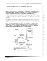
Page 6: ...ht paths are only necessary to obtain the maximum range obstructions in the radio path will reduce the range however may not prevent a reliable path Care must be taken with placement of antenna in rel...

Page 7: ...the TX RX connector An RF Path Link Budget must be calculated by a qualified technician prior to defining the following Location of the RADIO 900M Antenna type and location Length of cable run s and...

Page 8: ...Top of RADIO 900M 6 Using the 2 conductor cable provided in the RADIO 900M connect the DC power from the and supply connectors on the terminal block located on bottom of the RADIO 900M to pins 1 and...

Page 9: ...on the top of the IPC to the RJ 45 connector located on the bottom of the RADIO 900M 8 The RADIO 900M installation is complete close and secure the enclosure 9 Refer to the IPC 8000 Installation Instr...

Page 10: ...enclosure mount the DIN Rail Bracketto the mounting holes on the back panel of the HPSA 8100 R to the left of the control panel as shown in Figure 9 2 Mount the RF connector bracket to the mounting ho...

Page 11: ...closure and as close to the RF entry point as possible 2 Connect the RF cable from the Antenna to the N type Female connector on the SPD 3 Connect the RF Cable exiting the HPSA or IPC 8000 cabinet to...

Page 12: ...ide reasonable protection against harmful interference when the equipment is operated in a commercial environment This equipment generates uses and can radiate radio frequency energy and if not instal...

Reviews: