Installation into the IPC-8000
Installation Instructions: RADIO-900M
P/N P01-04941 Rev-A
I
N
S
T
A
L
L
A
T
I
O
N
I
N
S
T
R
U
C
T
I
O
N
S
8
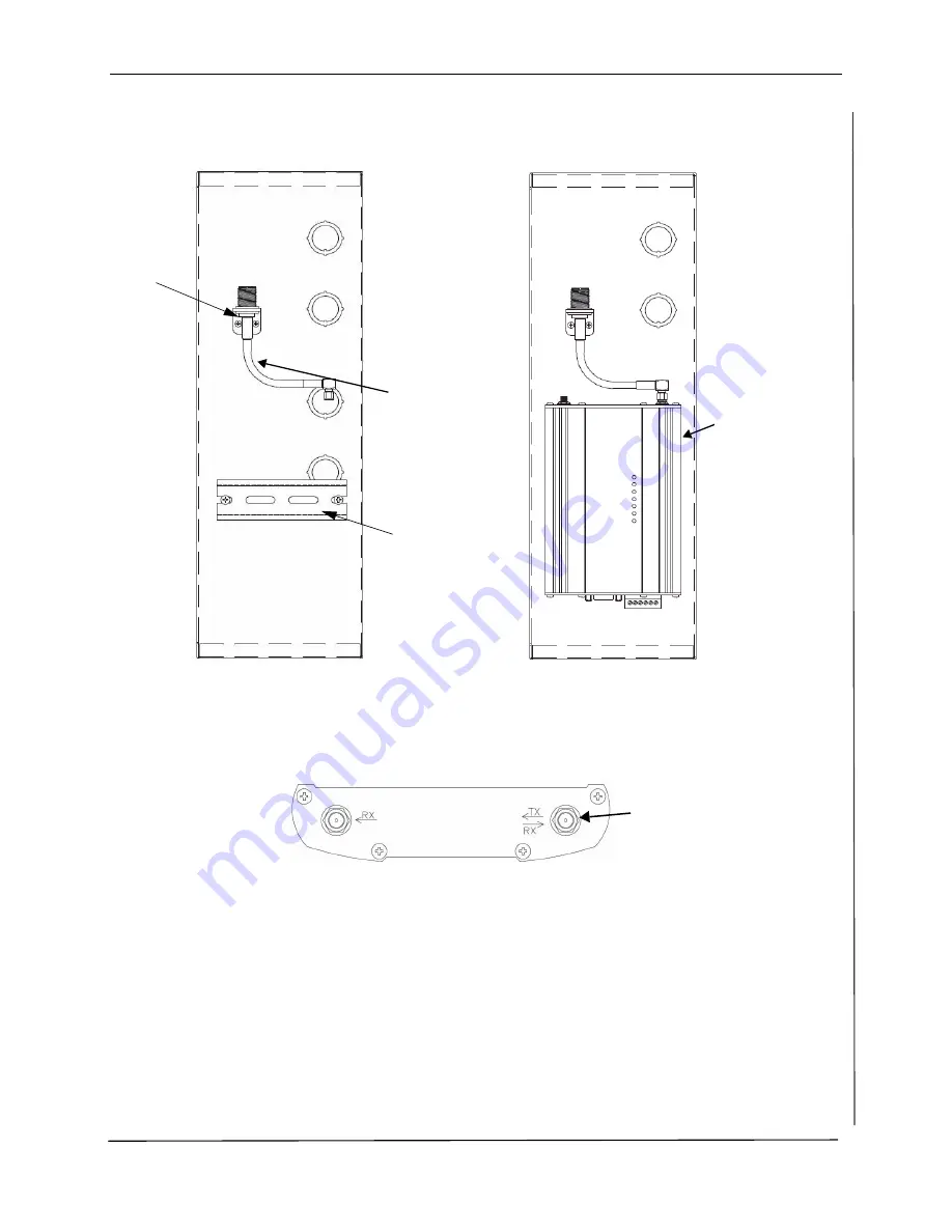
Figure 2 RF Bracket, Cable, and DIN Rail Bracket
Figure 3 Attaching the RADIO-900M
5.
Connect the RF Cable
to the TX/RX SMA connector on the top of the RADIO-900M
Figure 4 Top of RADIO-900M
6.
Using the 2-conductor cable provided in the RADIO-900M,
connect the DC power
from the
(+) and ( -) supply connectors on the terminal block located on bottom of the RADIO-900M
to pins 1 (+) and 2 (-) respectively of the is15 VDC output of the J8 connector located
on the top of the IPC unit.
Refer to Figure 5 for a wiring diagram between the RADIO-900M and IPC; refer to Figure 6
and Figure 7 for the connector locations.
DIN Rail
Bracket
RF
Cable
RF
Connector
Bracket
RADIO-900M
TX/RX SMA
connector

