Installation into the IPC-8000
Installation Instructions: RADIO-900M
P/N P01-04941 Rev-A
I
N
S
T
A
L
L
A
T
I
O
N
I
N
S
T
R
U
C
T
I
O
N
S
9
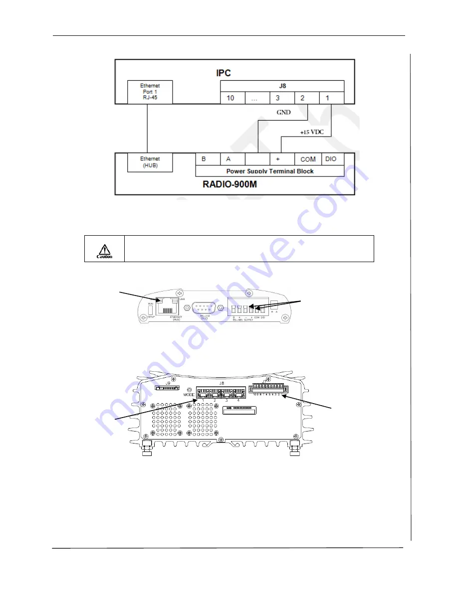
Figure 5 IPC-RADIO-900M Ethernet and Power Connections
Figure 6 Bottom View of RADIO-900M
Figure 7 Top View of IPC
7.
Connect the Ethernet cable
from the Port 1 Ethernet connector located on the top of the IPC
to the RJ-45 connector located on the bottom of the RADIO-900M.
8.
The RADIO-900M installation is complete;
close and secure the enclosure
.
9.
Refer to the IPC-8000 Installation Instructions for additional wiring and application
information.
The Power Supply’s negative side is connected to the unit case internally. The DC
Supply may be a floating supply or negatively grounded to the HPSA, ACU or
IPC-8000’s enclosure.
Ethernet
Port 1
IPC J7
DC Power Connector
RJ-45
Connector
The
– and +
terminal block
connectors

