background image

DVR User Manual 

39 

5


Search, Playback & Backup


Search configuration includes four submenus: time search, event search, file management and 
image. 
 

5.1  Time Search   

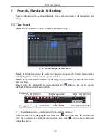
Step 1

: Enter into Menu

Search 

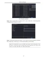
Time Search. Refer to Fig 5-1: 


Fig 5-1 Search Configuration-Time Search 


Step 2

: Select date and channels on the right hand side and press the „Search‟ button. A date 

with highlighted borderline indicates presence of data. 

Step 3

: Set the start time by clicking a particular grid or by entering the specific value in the 

start time field. 

Step  4

:  Select  the  channel  display  mode  and  click  Play 

  button  to  play  record.  Use  the 

playback toolbar to control the playback. 


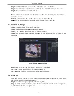
To set backup during a certain period in the playback interface: 

Select the start time by dragging the slider and click 

  icon. Then select the end time and 

click this icon again to confirm the record period. Next, click 

  icon to backup the record 

during this period. 
 

Summary of Contents for DVR2316SE-C

Page 1: ...DVR User Manual For H 264 4 8 16 channel digital video recorder All rights reserved ...

Page 2: ...normal recording condition The correct operation to shut off DVR is to stop recording firstly and then to select shut down button at the right of the menu bar to exit and finally to cut off the power This machine is indoor using equipment Do not expose the machine in rain or moist environment In case any solid or liquid get into the machine s case please cut off the power supply immediately and as...

Page 3: ...ower On 9 3 1 2 Power Off 9 3 2 Login 9 3 3 Live Preview 10 3 4 Live Playback 10 4 Main Menu Setup Guide 12 4 1 Basic Configuration 13 4 1 1 System 13 4 1 2 Time Date 14 4 1 3 DST 14 4 2 Live Configuration 15 4 2 1 Live 15 4 2 2 Main Monitor 16 4 2 3 Spot 17 4 2 4 Mask 17 4 3 Record Configuration 18 4 3 1 Enable 18 4 3 2 Record Bitrate 19 4 3 3 Time 19 4 3 4 Stamp 20 4 3 5 Recycle Record 21 4 3 6 ...

Page 4: ... 2 Event Search 40 5 3 File Management 40 5 4 Search by Image 41 5 5 Backup 41 6 Manage DVR 43 6 1 Check System Information 43 6 1 1 System Information 43 6 1 2 Event Information 43 6 1 3 Log Information 43 6 1 4 Network Information 43 6 1 5 Online Information 43 6 1 6 Record Information 43 6 2 Manual Alarm 43 6 3 Disk Management 43 6 4 Upgrade 44 6 5 Logoff 44 7 Remote Surveillance 45 7 1 IE Remo...

Page 5: ...nfiguration 54 7 6 Tools 55 7 7 Remote Management 55 Appendix A FAQ 56 Appendix B Calculate Recording Capacity 60 Appendix C Compatible Devices 61 Appendix D 4 CH DVR Specifications 62 Appendix E 8 CH DVR Specifications 63 Appendix F 16 CH DVR Specifications 64 ...

Page 6: ...display Display the local record state and basic information Supports USB to make full control RECORD MEDIA Supports one SATA HDD to record for a longer time without any limitation BACKUP Supports USB 2 0 devices to backup Supports saving recorded files with AVI standard format to a remote computer through internet RECORD PLAYBACK Record modes Manual Schedule Motion detection and Sensor alarm reco...

Page 7: ...e live view Supports 1 administrator and 63 users Supports event log recording and checking events unlimited NETWORK Supports TCP IP DHCP PPPoE DDNS protocol Supports IE browser to do remote view Supports setup client connection amount Supports dual stream Network stream is adjustable independently to fit the network bandwidth and environment Supports picture snap and color adjustment in remote li...

Page 8: ...HDD as Fig 2 2 Fig 2 1 Connect HDD Fig 2 2 Screw HDD Note For convenience installation please connect the power and data cables first and then wind the screws to fix the HDD 2 2 Front Panel Descriptions Notice The front panel descriptions are only for reference please make the object as the standard Type Name Description Work state indicator Power The power indicator turns blue when DVR is powered...

Page 9: ...e direction to select items Multi screen Change screen display mode like1 4 8 channel Enter button Confirm selection IR receiver IR For remote controller USB USB port To connect external USB devices like USB flash USB HDD for backup or update firmware or connect to USB mouse POWER POWER Switch off 2 3 Rear Panel Instructions Fig 2 3 Rear Panel for 4 ch Item Name Description 1 Audio out Audio outpu...

Page 10: ...t Connect to external alarm 4 ALARM IN Connect to external sensor 1 8 5 Video in Video input channels from 1 8 6 VGA port VGA output connect to monitor 7 HDMI port Connect to high definition display device 8 LAN Network port 9 USB port Connect USB mouse or connect external USB devices 10 DC12V POWER INPUT 11 RS485 Connect to speed dome or keyboard 12 Audio out Audio output connect to the sound box...

Page 11: ...l by channel Video would be displayed without OSD 2 4 Remote Controller It uses two AAA size batteries Step 1 Open the battery cover of the remote controller Step 2 Place batteries Please take care the polarity and Step 3 Replace the battery cover Fig 2 6 Remote Controller Button Function REC Record manually Search To enter search mode MEUN To enter menu Exit To exit the current interface ENTER To...

Page 12: ...g live Double click on any camera window to see the full screen Double click again to return to the previous screen Right click to reveal the control menu on the screen Right click again to hide the menu In Configuration Click to enter a particular option Right click to cancel the option or to return to the previous menu In order to input a value in a particular screen move cursor to the input box...

Page 13: ...mode In Backup Click to choose the options Right click to return to previous picture In PTZ Control Click left button to choose the buttons to control the PTZ Click right button to return to live Note Mouse is the default tool for all operations unless an exception as indicated ...

Page 14: ...t of time if there is live image display without menu options then please check if there is display on other device monitor or long press ESC key to wait for login dialog box to appear Long press ESC key can switch the output between BNC and VGA HDMI 3 1 2 Power Off User can power off the device by using remote controller keyboard and mouse By remote controller Step 1 Press Power button This will ...

Page 15: ...ng users please refer to section 4 7 User Management Configuration 3 3 Live Preview Fig 3 2 Live Preview Interface 3 4 Live Playback Click Play button to playback the record Refer to Fig 3 3 User can do complete operation by clicking the buttons on screen Symbol Meaning Green Manual record Yellow Motion detection record Red Sensor Alarm record Blue Schedule record ...

Page 16: ...DVR User Manual 11 Fig 3 3 Live Playback ...

Page 17: ...enabled only when the chosen display mode is not able to display all the available cameras Color If this button is enabled you can adjust the color of live pictures E Zoom Single channel large screen electronic amplification Audio Enable sound PTZ Click the PTZ button to control rotation position speed and auto scan of the PTZ Snap Click this button to snap the live pictures These pictures will au...

Page 18: ...so on The definitions for every parameters display as below Device Name The name of the device It may display on the client end or CMS that help user to recognize the device remotely Device ID This ID is used to map the DVR with IR remote controller and speed dome cameras Video Format Two modes PAL and NTSC User can select the video format according to that of camera 960H Mode This function is onl...

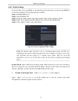
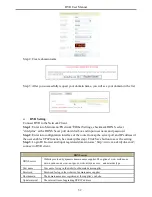
Page 19: ...rval time 30s 60s 180s 300s If there is no any operation within the setting period the device will auto logout and return to login interface Show Wizard If selected the GUI would launch the startup wizard on every boot allowing the user to do basic setup No Image When Logout If selected there will be no image showing when logging out 4 1 2 Time Date Step 1 Enter into Menu Setup Basic Date Time int...

Page 20: ...ve In this interface you can setup camera name and adjust colors To setup camera name Step 1 Enter into Menu Setup Live Refer to Fig 4 6 Fig 4 6 Live Configuration Live Step 2 A software keyboard will pop up by clicking camera name area Click the letters and or digital numbers on the keyboard to input the name you want to display in live image Step 3 Checkmark the camera name in the show name area...

Page 21: ...n Monitor The main monitor settings allow you to set camera sequence in live display mode Operate the following steps to set main monitor Step 1 Enter into Menu Setup Live Main Monitor interface Refer to Fig 4 8 Fig 4 8 Live Configuration Main Monitor Step 2 Select display mode and channel Step 3 Select dwell time Click button to setup the previous channel groups of dwell picture Click button to s...

Page 22: ...lect the display mode and setup current picture group Step 5 Click Apply button to save the settings 4 2 4 Mask If there is something you don t want to display in the live image You can set mask For a given channel a maximum of three areas can be masked To setup mask area Step 1 Enter into Menu Setup Live Mask interface Fig 4 10 Live Configuration Mask Step 2 Click Setting button to go into live i...

Page 23: ...he setting Setup Mask Area 4 3 Record Configuration Record configuration includes six sub menus enable record bit rate time recycle record stamp and snap Before Configuration please make sure your DVR has been installed with HDD and has completed its initialization 4 3 1 Enable Step 1 Enter into Menu Setup Record Enable interface Refer to Fig 4 11 Fig 4 11 Record Configuration Enable Parameter Mea...

Page 24: ... isn t enabled in 8 16 CH DVR the resolution option includes D1 HD1 and CIF and the maximum number of frame you can choose is 25 PAL 30 PAL 4 3 3 Time Step 1 Enter into Menu Setup Record Time interface to set recording time Refer to Fig 4 13 Step 2 Set Pre alarm record time and post alarm record time Select All to set the same settings for all channels Pre alarm Record Time Set the time in seconds...

Page 25: ...he setting Fig 4 13 Record Configuration Time 4 3 4 Stamp This provides an option to enable or disable the Camera Name and the Time stamp on the video The user can also choose a position for the stamp on the screen To setup stamp as follows Step 1 Enter into Menu Setup Record Stamp interface Refer to Fig 4 14 Fig 4 14 Record Configuration Stamp Step 2 Checkmark camera name and time stamp Click Set...

Page 26: ...4 3 6 Snap In this interface user can set up Resolution quality snap interval snap number 4 4 Schedule Configuration Schedule configuration includes three sub menus schedule motion and sensor 4 4 1 Schedule This tab allows defining schedule for normal recording for seven days of a week 24 hours of a day Every row denotes an hourly timeline for a day Click the grid to do relevant setup A highlighte...

Page 27: ...ttings To item Schedule Week Schedule 4 4 2 Motion Schedule This tab allows to set schedule for motion based recording The setting steps are as follows Step 1 Enter into Menu Setup Schedule Motion tab Step 2 The setup steps for schedule for motion based recording are similar to normal schedule setup You can refer to 4 4 1 Schedule for details Note The default schedule of motion based recording is ...

Page 28: ...4 5 Alarm Configuration Alarm configuration includes five sub menus sensor motion video loss other alarm and alarm out 4 5 1 Sensor Alarm Sensor includes three sub menus basic alarm handling and schedule Operate the following steps to configure sensor alarm Step 1 Enter into Menu Setup Alarm Sensor Basic interface Refer to Fig 4 16 Fig 4 16 Alarm Configuration Sensor Basic Step 2 Enable channels b...

Page 29: ...d email address in case of a sensor based alarm from the particular input Snap If selected the system will snap images of the checked channels on an alarm and save them in the HDD automatically Step 7 Enter into To Record tab Select recording channels It would be recorded in case of an alarm Click OK button to save the setting Step 8 Enter into To PTZ tab Set preset cruise and track options for a ...

Page 30: ...arm specific to channel until 10 seconds If there is other motion detected during this period it is considered it as continuous movement otherwise it will be considered as a single motion Step 3 The setup steps of motion trigger are similar to Alarm Handling See Chapter 4 5 1 Sensor Alarm Handling setting for more details Step 4 After clicking Area button a dialog box will pop up as Fig 4 20 Step ...

Page 31: ...alarm are similar to normal schedule setup see Chapter 4 4 1 for more details 4 5 3 Video Loss This DVR can be set up to detect video loss The setting steps are as follows Step 1 Enter into Menu Setup Alarm Video Loss Refer to Fig 4 21 Step 2 The setup steps of video loss trigger are similar to Alarm Handling See Chapter 4 5 1 Sensor Alarm Handling setting for more details Fig 4 21 Alarm Configura...

Page 32: ...ll trigger the Disk Full Alarm Step 4 Click Apply to save the setting F 4 5 5 Alarm Out Alarm out includes three sub menus alarm out schedule and buzzer To setup alarm out Step 1 Enter into Menu Setup Alarm Out Refer to Fig 4 23 Fig 4 23 System Configuration Alarm Out Step 2 Input relay name and select hold time Step 3 Enter into Schedule tab This will go into schedule setup interface The setting ...

Page 33: ...P port is 80 If the value is changed you shall add the port number when typing IP address in IE address blank e g If HTTP port is set to 82 and IP address is http 192 168 0 25 you should input the following IP address http 192 168 0 25 82 into IE browser Step 3 Set server port The default server port is 6036 Step 4 Connect internet There are three ways to connect internet If you have a DHCP server...

Page 34: ...Select fps resolution quality encode and max bit rate Step 3 Select All to set the same settings for all channels Fig 4 25 Network Configuration Sub Stream 4 6 3 Email To set up Email Step 1 Enter into Menu Setup Network Email interface Refer to Fig 4 26 Step 2 Set SMTP Server and port SMTP Server Port The name and port number of SMTP server You can setup SSL check such as Gmail according to actua...

Page 35: ...ork Configuration Server Step 2 Check the IP address and port of the transfer media server in the ECMS NVMS The default server port for auto report is 2009 If it is modified please enter into the transfer media interface to check Step 3 Enable the auto report in the ECMS NVMS when adding a new device Then input the remaining information of the device in the ECMS NVMS After that the system will aut...

Page 36: ...ser is a banding domain name of DVR User should logon the website which provided by the server supplier to register a user name and password and then apply for a domain name online After the successful application user can access the device from the IE client by inputting that domain name Enable UPnP Select UPnP here and then enable UPnP function in your router Therefore there is no need for you t...

Page 37: ...ss if the user enables UPnP function he can skip this step Click Save button to save the setting Step 3 Login IE browser and input registered domain name http www xxx dvrdydns com connect to DVR client DDNS server DDNS server Website provided by dynamic domain name supplier The optional www meibu com www dyndns com www no ip com www dvrdydns com and mintdns type User name User name for log in the ...

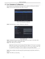
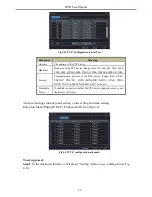
Page 38: ...ral tab input username password and select user type You can also check Binding PC MAC Address and input this address Step 4 Click OK to save the setting Note When the default value of binding PC MAC Address is 0 the user is not bound with the specified computer If the bind option is used the user would be able to log into the DVR only through the specific computer carrying the MAC address Step 5 ...

Page 39: ...n To change user password Step 1 Enter into Menu Setup Users interface Step 2 Select the added user you want to change its password and then click Change Password button 4 8 P T Z Configuration P T Z configuration includes two submenus serial port and advanced Serial port settings are as follows Step 1 Enter into Menu Setup P T Z Serial Port interface Refer to Fig 4 32 Step 2 Select Enable and set...

Page 40: ...et Setting button to see a dialog box as Fig 4 34 Parameter Meaning Address The address of the PTZ device Baud rate Baud rate of the PTZ device Range form 110 300 600 1200 2400 4800 9600 19200 34800 57600 115200 230400 460800 921600 Protocol Communication protocol of the PTZ device Range from NULL PELCOP PELCOD LILIN MINKING NEON STAR VIDO DSCP VISCA SAMSUNG RM110 HY N control Simulative Cruise If...

Page 41: ...l number of the preset point Click button to enable the PTZ wiper and click button to enable the PTZ light Note PTZ must support wiper and light button and these two buttons are just available when selecting PELCOP or PELCOD Step 5 Click Save button to save the setting Click icon to hide the tool bar Right click to view this bar again Click icon to exit the current interface Step 6 Return to the A...

Page 42: ...of preset point Click Preview button to preview the cruise line Click OK button to save the setting To set up track Step1 In the Advanced interface click track Setting button to see a dialog box as Fig 4 38 Step 2 Control the dome by rotating up up left down right down left left down right and up right and adjust the rotate speed and the value of zoom focus and iris of the dome Step 3 Click Start ...

Page 43: ... 3 Block Allow List Fig 4 39 Block Allow List Here authorized user can prohibit computer users within a certain IP address range from accessing to DVR or allow computer users within a certain IP address range to access DVR E g if an admin user doesn t want computer users within IP address range from 192 168 000 002 to 192 168 000 004 to access the DVR he can check Block list option and then input ...

Page 44: ...h highlighted borderline indicates presence of data Step 3 Set the start time by clicking a particular grid or by entering the specific value in the start time field Step 4 Select the channel display mode and click Play button to play record Use the playback toolbar to control the playback To set backup during a certain period in the playback interface Select the start time by dragging the slider ...

Page 45: ... presence of data Step 3 Checkmark Motion Sensor or All accordingly Step 4 Click Search button to display the searched event information in the event list box Step 5 Double check a certain record file to playback 5 3 File Management Step 1 Enter into Menu Search File Management interface Refer to Fig 5 3 Fig 5 3 Search Configuration File Management Step 2 Select date and channels The date with hig...

Page 46: ...ab Step 2 Select data and channels on the right hand side Step 3 Press Search button to search for a recorded image Step 4 Once an alarm image has been identified the user can double click the image to play recording Fig 5 4 Search Configuration Image Lock Select the image and click Lock button to lock this image Save Click Save button to copy the image on the HDD Save All Click Save All button to...

Page 47: ... In the backup information interface you can check the relevant information of backup files storage type save file type etc Then click Start button to start backup Note If the backup files are saved in DVR format please check backup player Only this player can play these files in DVR format If the backup files are saved in AVI format you can play these files with common media player ...

Page 48: ... which includes Operation Setup Playback Backup Search Check Information and Error This report can further be saved on a USB flash drive as an html file using the export button 6 1 4 Network Information In this interface you can check relevant parameters of network 6 1 5 Online Information In this interface you can check the details of the connected online users Refresh Refresh the current interfa...

Page 49: ... so as to protect its data 6 4 Upgrade At present it only supports USB update Get the software from your vendor when there is a new software version The upgrade steps are as follows Step 1 Copy the upgrade software which gets from vendor into the USB storage device Step 2 Connect the USB flash drive to the USB port Step 3 Enter Menu Upgrade tab You will see the upgrade software name displaying in ...

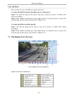
Page 50: ...sed on the DVR The default username and password is admin and 123456 7 1 2 On WAN There are two ways for the DVR to connect to internet 1 Connect the DVR to internet through router or virtual server Step 1 Enter into the DVR s Main Menu Setup Network interface to input IP address Subnet Mask etc If using DHCP please enable DHCP in both the DVR and router Step 2 Forward IP address and port number i...

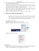
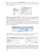
Page 51: ... The following setting steps are as the same as Step 4 and Step 5 in Point 1 7 2 Remote Surveillance through Apple PC Note Because the current plug in version of client end just only supports 32 bit mode so the safari browser shall start 32 bit mode If the browser is the earlier MACOS version the default setting is 32 bit mode and the setting can be skipped The setting steps are as follows Step 1 ...

Page 52: ...in the Safari browser For example input http 192 168 1 100 81 here 192 168 1 100 is LAN IP of DVR 81 is the http port of DVR and click button Then the browser will download Active X control as shown below Step 5 Click icon and then select the Active X control the welcome interface will be shown Click Continue Install button the following window will pop up Input the name and password of Apple PC a...

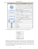
Page 53: ... 6 of Chapter 7 2 1 2 Connect the DVR to internet directly Step 1 The network setups are the same as step one of point 2 on WAN of IE remote surveillance Step 2 Enter WAN IP and http port in the Safari browser to install the Active control The concrete steps are the same as step 5 and 6 of Chapter 7 2 1 7 3 The Remote Live Preview Fig 7 1 Remote Live Preview Interface Symbol and function definitio...

Page 54: ...nd Saturation Click Default to reset them to original value Buttons Description Drag the scroll bar to adjust the brightness of channel Drag the scroll bar to adjust the contrast of channel Drag the scroll bar to adjust the saturation of channel Drag the scroll bar to adjust the hue of channel Click this button to recover the default value of brightness contrast saturation and hue Save the adjustm...

Page 55: ...oom in the locale picture of this camera Click button near Zoom button to zoom out the locale picture of this camera Focus button Click button near Focus button to have long focus Click button near Focus button to have short focus Go to the Preset Select and do auto cruise Track Auto scan Wiper button Light button Click the right mouse on the live interface This will take you to a pull down menu F...

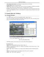
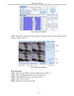
Page 56: ... 7 4 1 Remote Playback Click button to go into record playback interface Refer to Fig 7 3 Select the record date and channels and double click the file name in the record file list box Then you can play that file and preview the picture Fig 7 3 Play Record File Interface This DVR supports remote time search event search and file management By Time Search Step 1 Enter into Search Time Search Refer ...

Page 57: ... change channel mode etc Refer to Fig 7 5 Fig 7 5 Time Search Playback By Event Search Step 1 Enter into Search Event Search interface Refer to Fig 7 6 Step 2 Click the highlight date and select record channels Step 3 Checkmark the event type motion and sensor Step 4 Click Search button Step 5 Double click certain item to play ...

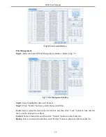
Page 58: ...ighlighted date and channels Step 3 Click Search button to search the recorded files Lock Select certain file item in the file list box and then click Lock button to lock this file that ca not be deleted or overlaid Unlock Select a locked file and then click Unlock button to unlock this file Delete Select an unlock file and then click Delete button to delete this file from file list ...

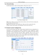
Page 59: ...ote System Configuration You can do remote setup of the device which includes functions like basic configuration live configuration record configuration schedule configuration alarm configuration network configuration PTZ configuration and user configuration You should select an option from the menu list on the left and then setup the relative parameters Only one user can do configuration setup at...

Page 60: ... hard drive s 7 7 Remote Management The Info interface provides a web based interface to access the general information pertaining to the DVR s settings The interface includes five submenus System Event Log Network and Online users Note There may be subtle differences with respect to functions of remote surveillance between through IE and through Apple PC Here we only take IE remote access for exa...

Page 61: ...r settings Q4 Why are no images displayed on few or all channels of the DVR a It could be a wiring issue Please check the cable and the ports of the cameras and DVR b The problem can also be related to cameras Please check the same c Please make sure that the channels are not programmed as hidden channels and check the status from admin login Q5 The HDD cannot be found a The power from the adapter...

Page 62: ... Custom Level Refer to Fig 8 1 Step 3 Enable all the sub options under ActiveX controls and plug ins Refer to Fig 8 2 Then click Ok to finish setup b Other plug ins or anti virus blocks ActiveX Please uninstall or do the required settings Fig 8 1 Fig 8 2 Q9 DVR displays please wait all the time a HDD power cable and data cable may not be well connected Please check the connections for HDD b It is ...

Page 63: ...ns a HDD the migrated disk being installed would have to be formatted In general migrating disks from one DVR to another is not recommended Q12 What is the minimum configuration required for remote monitoring PC Module Parameters CPU Intel Celeron 2 4G Motherboard Intel 845 HDD 80G RAM 512M VGA NVIDIA GeForce MX440 FX5200 ATIRADEON 7500 X300 OS Windows 2000 SP4 above Windows XP SP2 above VISTA Dir...

Page 64: ... double click to open your USB disk to find your backup files and backup player Double click icon to install backup player After you install it open this player and click Open Path button to open your backup file Next click play button to play the backup file Double click the image and then right click to enable audio If you save your backup files in AVI format you can directly open your file by u...

Page 65: ...00 Higher 1 5M 675 Medium 1M 450 Low 768 338 The calculation format is Total Recording capacity Used space per hour MB h coverage rate of hard disk recording time hour channel numbers For instance one customer uses NTSC cameras set resolution to D1 video quality to Low frame rate to 30 fps for enabling total 4 channels Below is the calculation to record continuously for a month Total Recoding capa...

Page 66: ...ty SSK 512MB 1G 2GB Netac 4GB Kingston 2GB Aigo 2GB Smatter vider 1GB SanDisk 4GB 2 Compatible HDD list Brand Capacity Seagate Barracuda 80G 160G 250G 320G 1 5T 2TB Seagate SV35 3 1T Seagate Pipeline HD 2 500G Maxtor Diamondmax 160G HITACHI Deskstar 80G 160G WD WD1600JS 160G Samsung HD161HJ 160G ...

Page 67: ...Display Frame Rate 100FPS PAL 120FPS NTSC Record Frame Rate 100FPS PAL 120FPS NTSC Audio Input RCA X4 Audio output RCA X1 Alarm Input NO or NC 4CH Alarm output 1CH Record Mode Manual Sensor Timer Motion detection Simplex Duplex Triplex Pentaplex Network Interface RJ45 LAN INTERNET PTZ control YES Communication interface RS485 USB2 0 x 2 one for backup another for USB mouse Disk info SATA x 1 Remot...

Page 68: ...Frame Rate 200FPS PAL 240FPS NTSC Record Frame Rate 100 200 200FPS PAL 120 240 240FPS NTSC Audio Input RCA X4 Audio output RCA X1 Alarm Input NO or NC 8CH Alarm output 1CH Record Mode Manual Sensor Timer Motion detection Simplex Duplex Triplex Pentaplex Network Interface RJ45 LAN INTERNET PTZ control YES Communication interface RS485 USB2 0 x 2 one for backup another for USB mouse Disk info SATA x...

Page 69: ...Frame Rate 400FPS PAL 480FPS NTSC Record Frame Rate 200 400 400FPS PAL 240 480 480FPS NTSC Audio Input RCA X4 Audio output RCA X1 Alarm Input NO or NC 16CH Alarm output 1CH Record Mode Manual Sensor Timer Motion detection Simplex Duplex Triplex Pentaplex Network Interface RJ45 LAN INTERNET PTZ control YES Communication interface RS485 USB2 0 x 2 one for backup another for USB mouse Disk info SATA ...

Page 70: ...A0 ...

Page 71: ...Quick Start Guide 4 8 16 CH DVR ...

Page 72: ......

Page 73: ...e screws to fix the HDD 2 Rear Panel Connection Rear Panel for 4 CH Item Name Description 1 Audio out Audio output connect to the sound box 2 Audio in 4 CH Audio input 3 ALARM IN Connect to external sensor 1 4 4 ALARM OUT 1 ch relay output Connect to external alarm 5 GND Grounding 6 Video in Video input channels from 1 4 7 CVBS port Connect to monitor 8 Spot out Connect to monitor as an AUX output...

Page 74: ...nsor 1 8 5 Video in Video input channels from 1 8 6 VGA port VGA output connect to monitor 7 HDMI port Connect to high definition display device 8 LAN Network port 9 USB port Connect USB mouse or connect external USB devices 10 DC12V POWER INPUT 11 RS485 Connect to speed dome or keyboard 12 Audio out Audio output connect to the sound box 13 CVBS port Connect to monitor 14 Spot out Connect to monit...

Page 75: ... as an AUX output channel by channel Video would be displayed without OSD 3 Startup Shutdown 3 1 Startup Step1 Connect to cameras and monitor Step2 Connect with the source power Step3 The device will boot and the power indicator will display blue Step4 A WIZZARD window will pop up 3 2 Shutdown You can shut down the device by using IR remote controller and mouse By IR remote controller Step1 Press ...

Page 76: ...to bring up a network setup window The default HTTP port is 80 The default server port is 6036 You can check Obtain an IP address automatically to acquire network information or input IP address subnet mask gateway preferred alternate DNS server manually This function is used to monitor DVR through internet See Section 10 for details Click Next button This will take you to record setup window Sele...

Page 77: ... Wizard please click Exit button to exit 5 Login After you exit the wizard setup you can login to the DVR Notice This DVR can only display options on either VGA HDMI monitor or BNC monitor at a given point of time if there is live image display without menu options please check if there is display on other device monitor or long press ESC Stop key to wait for login dialog box to appear Long press ...

Page 78: ...tion Administrator can add delete users and change their authorization PTZ configuration Users can set protocol baud rate address presets and auto cruise track here Advanced configuration Users can reboot the device and import export data into or from mobile storage medium 7 Recording Setup A user needs to install and format a HDD and set all the recording parameters before recording There are fou...

Page 79: ...chedule Step 4 Select other channels and set timeline for them or select Apply Settings To All Channel and click Copy button to set the same settings for all channels 7 3 Motion Based Recording Motion detection based recording when there is a motion event detected the camera will be triggered to record To Setup Motion Based Recording Step 1 Enter into Menu Setup Schedule Motion tab The setup steps...

Page 80: ...a Click icon to test the sensitivity as per the local conditions Once motion is sensed it displays a figure icon Click icon to save the setting Click icon to exit the current interface Step 5 Enter into Menu Setup Alarm Motion Schedule tab to bring up schedule settings for motion alarm The setup steps are similar to normal schedule setup You can refer to 7 2 Schedule Recording for details Note The...

Page 81: ...gs for sensor alarm The setup steps are similar to normal schedule setup You can refer to 7 2 Schedule Recording for details Note The timelines of the two schedules must match otherwise you cannot get the record in some time 8 Playback This unit supports four kinds of playback 8 1 Live Playback Click Play button on the main menu bar to playback the record User can do concrete operation by clicking...

Page 82: ...r grid or by entering the specific value in the start time field Step 4 Select the channel display mode and click button to play record Use the playback toolbar to control the playback 8 3 Playback by Event Search Step 1 Enter into Menu Search Event Search tab Step 2 Select date and channels on the right hand side A data with highlighted borderline indicates presence of data Step 3 Then checkmark ...

Page 83: ...lick Save All to copy all images on the HDD Note In order to take images on alarm the snapshot feature should be activated in Alarm Handling for different kind of alarms Please refer to Alarm Configuration for details 9 Back up This unit supports backup by USB flash Step 1 Enter into Menu Backup tab Step 2 Set the start end time select channels and click Search button to display the searched data ...

Page 84: ...bnet Gateway If using DHCP please enable DHCP in both the DVR and the router Enter into Menu Information Network and user can check the network settings of the DVR Enter into Record Setup to set network video parameters like resolution frame rate etc Open IE on a computer on the same network Input the IP address of the DVR in IE address bar and press enter If HTTP port is not 80 add the port numbe...

Page 85: ...mber after IP address or domain name IE will download ActiveX automatically Then a window pops up and asks for user name and password Input name and password correctly and enter to view 2 Connect the DVR to Internet through PPPoE Enter into the DVR s Main Menu Setup Network interface to enable PPPoE and then input user name and password received from your ISP Next click Apply The DVR will connect ...

Reviews: