363-765-104-04
February 19, 1998
Revision
04
FRE-765
List
4x
PairGain
Engineering - Plant Series
15
For pole mounting the FRE-765, use the Pole Mounting kit, part number 150-1397-0x. Follow the instructions
that are included to install the pole mounting bracket. Then mount the FRE-765 to the bracket. Do not install any
cabling until the FRE-765 is securely mounted.
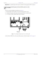
When required, install the grommet into the base of the FRE-765 (see
Figure 8
) prior to performing any wiring
(
Table 11
shows the wire gauges that you can install through the holes in the grommet):
1
Select only one concentric knockout hole on the FRE-765.
2
Remove the largest knockout so that the entire hole is open.
3
Install the grommet from the outside of the FRE-765.
(Hint - Hold it at an angle to the hole and roll it into position.)
4
Ensure that the lip of the grommet rests on the bottom of the FRE-765 around the knockout hole.
5
Use an appropriate tool to open the required hole(s) in the bottom of the grommet.
Figure 8.
Installing the Grommet
*
Recommend using one hole for both the HDSL and the bypass pairs (i.e., 6-pair cable) and using the second hole for
POTS (subscriber) lines.
†
Dependent upon gauge of wire used.
Table 11.
Grommet Hole Diameters
For this grommet hole size
Use this cable
.410 to .765 in. diameter (two)
*
•
24 or 26 AWG, 25- or 50-pair Primary Interexchange Carrier (PIC) (filled or
non-filled)
•
22 AWG, 25-pair PIC (filled or non-filled)
•
22, 24, or 26 AWG , 6- or 11-pair PIC (filled or non-filled)
.240 to .275 in. diameter (one)
ground wire
†
.155 to .240 in. diameter (one)
ground wire
†

