
Overview
950-779-115-02, Revision 02
2
March 17, 2000
PRL-770 and PRL-779 List 1E and 2E
M
ETALLIC
F
ALLBACK
Metallic fallback provides a direct connection from the CO to subscriber number one under fault conditions. The
metallic fallback feature is a provisionable item. You can disable this feature through the user screens.
Service is provided to the subscriber assigned to the LS/GS line in the affected COLU. At the RT, the system exits
metallic fallback and attempts to synchronize if either LS/GS number one or the HDSL Tip to Ring pair is shorted
for at least 3 seconds, and then released for at least 3 seconds. Otherwise, the COLU checks for the presence of
an RT every 5 minutes. If an RT is present, the system begins HDSL synchronization acquisition.
Relays in the COLU and RT under control of the PG-Plus Alarm Unit (PAU) or PG-Plus Management Unit
(PMU) provide a path for subscriber drop test and metallic fallback operation. These relays are used to establish
a path to channel 1 of the LS/GS RT during fault conditions and to provide for drop testing of the selected
subscriber line from the CO location.
S
PECIFICATIONS
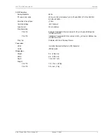
Power
Voltage Safety
A2 compliant per GR-1089-CORE
HDSL Line Input Voltage
+/-135 Vdc Tip to Ring, maximum
HDSL Line Start-up Voltage
+/- 100 Vdc Tip to Ring, minimum
RT Input Power
10.2 Watts typical; 11.2 Watts Tip to Ring, maximum with 4 off-hook, 2 ringing
5 REN
HDSL
Line Code
2B1Q
Line Rates
PRL-770
130.6 K symbols/sec; 262 Kbps
PRL-779
196 K symbols/sec (392 K bps), 261.3 Kbps
Line Reach
PRL-770
26 AWG (0.4 mm),15.0 kft (4.57 km)
24 AWG (0.5 mm), 21.7 kft (6.61 km)
22 AWG (0.6 mm), 31.2 kft (9.51 km)
19 AWG (0.9 mm), 49.7 kft (15.1 km)
PRL-779
26 AWG (0.4 mm), 12.5 kft (3.81 km)
24 AWG (0.5 mm), 18.0 kft (5.48 km)
22 AWG (0.6 mm), 25.2 kft (7.68 km)
19 AWG (0.9 mm), 37.8 kft (11.5 km)
Maximum Attenuation
PRL-770
45.9 dB at 65 kHz
PRL-779
41.6 dB at 98 kHz
Environment
Temperature
-40
F to +131
F (-40
C to + 55
C)
Humidity
5% to 95% noncondensing
Altitude
-200 ft. to 13,000 ft. (-60 m to 4,000 m)
Compliance
Human Safety
UL 1950
Emissions Radiation and Immunity
GR-1089 Core Class B and FCC Part 15 for Class B compliant


